Home

User Documentation

Getting Started
Learn More
Explore in Detail
Get Inspired

Contributor Documentation

Getting Started
Learn More
Explore in Detail
Get Inspired

Quick Links

Software Manual
AstroDiscuss
GitHub
API Reference

Documentation Versions

Public Release
8.1.0
8.0.0
7.2.0
7.1.0
7.0.0
6.0.0
3.9.0
3.5.0

ISIS 2

Documentation
Tutorials
Technical Documents
USGS

ISIS Application Documentation


shadow

Printer Friendly View | TOC | Home

Create a high accuracy hillshade with shadow casting

Overview Parameters Example 1 Example 2

Description

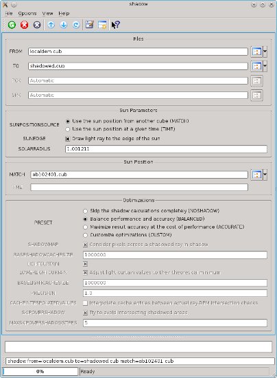
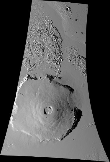
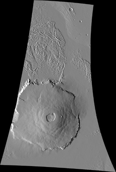
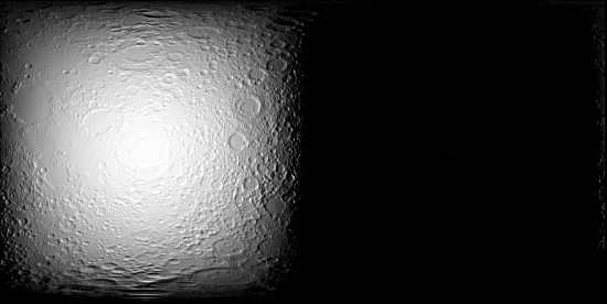
This program, shadow, will create a shaded-relief cube from a digital elevation model (DEM) and a MATCH cube.

We use the sun's position at the center of the input cube or a user-defined observation time. By default, we factor in shadows cast by features. This program operates much like the ISIS 'shade' program which instead requires azimuth/elevation as input.

However, with the shadow application, using the sun's position allows much higher precision shading and enables the possibility of computing shadowed areas. The algorithm description below is provided to help understand the optimization settings.

User-Requirements
The user must supply an elevation model (DEM) and either an observation time or a cube with raw camera geometry (see 'spiceinit'). If providing an observation time, the PCK and SPK SPICE kernels associated with the DEM's target must have been downloaded and be available on the user's machine in the "base" kernels area, or their file paths must be provided as values to the PCK and SPK user parameters.

Understanding the Algorithm
The 'shade' program's algorithm is called 'hillshade' in this algorithm description.
  1. Compute the sun's position at the center of the MATCH cube. The MATCH cube must have the same target as the DEM.
  2. For every pixel in the input elevation model, compute the hillshade value for the pixel, and
    1. if the hillshade result is positive (facing towards the sun), then estimate if the pixel is in shadow;
    2. if the hillshade value is positive and the pixel is in shadow, then the result is an LRS;
    3. if the hillshade value is positive and the pixel is not in shadow, then the result is the hillshade result and
    4. if the hillshade value is negative, the result is low resolution saturation (LRS).
The algorithm to estimate if a pixel is in shadow:
  1. Optimization: If SHADOW, and this elevation model pixel is known to be shadowed, consider this pixel to be shadowed and stop (no pixels are initially known to be shadowed).
  2. Compute the pixel's body-fixed coordinate (XYZ) position.
  3. If SUNEDGE, adjust the sun's position to nearer the highest (on the horizon) edge of the sun.
  4. Subtract the sun's position from the elevation model pixel's position, providing a vector to the center (or edge) of the sun.
  5. Iterate until a solution is found:
    1. Step along the 3D ray the current estimate of PRECISION pixels
    2. Project the ray back onto the elevation model to find the equivalent radius
    3. Update estimate of how far along the 3D ray is equivalent to the full resolution of the elevation model.
      Optimization: Multiply the step by PRECISION.
      Optimization : If SKIPOVERSHADOW, while the next linearly-extrapolated elevation model position is known to be in shadow, increase the next step size by the estimate up to MAXSKIPOVERSHADOWSTEPS times.
    4. Check for a solution
      • If the equivalent radius is higher than the ray, then the originating pixel is shadowed.
      • If the ray's elevation is higher than the highest point on the elevation model, the originating pixel is in light.
        Optimization: If LIGHTCURTAIN, and the ray's elevation is higher than a previous ray that intersected this pixel in the elevation model, consider the originating pixel in light.
    5. Optimize
      • If LIGHTCURTAIN, and the pixel was determined to be in light, record the elevations of the ray where it projected onto the elevation model.
        Optimization: If LOWERLIGHTCURTAIN, lower the elevations along the ray by subtracting the minimum difference between the ray and the elevation model while the ray was being walked.
        Optimization: If CACHEINTERPOLATEDVALUES, linearly interpolate the points where the ray would have intersected the elevation model to one pixel accuracy.
      • If SHADOWMAP, and the pixel was determined to be in shadow, record all points where the ray projected onto the elevation model to be known shadowed points, excluding the actual intersection point.
        Optimization: If CACHEINTERPOLATEDVALUES, linearly interpolate the points where the ray would have intersected the elevation model to one pixel accuracy.
The caches inherently cause inaccuracies (approximately 1-2 pixels if CACHEINTERPOLATEDVALUES is off) in the output shadow positions because they record sub-pixel values as if they were the center of the pixel. Periodically, the caches are shrunk to lower memory usage. The light curtain cache is shrunk to around BASELIGHTCACHESIZE entries and the shadow map cache is shrunk down to around BASESHADOWCACHESIZE entries. Each cache entry is approximately 24 bytes for the light cache, and 16 bytes for the shadow cache, but the caches are hash-based causing a large amount of potential overhead. The caches are not limited to their specified sizes, only reduced to them periodically, and larger cache sizes result in this program consuming more memory. The larger the cache, the longer it takes to lookup a single value (which happens often). In general, larger caches mean less CPU time for the cost of memory.

Categories


History

Steven Lambright2013-02-28 Original version.
Kristin Berry2015-07-22 Added NaifStatus::CheckErrors() to see if any NAIF errors were signaled. References #2248.
Kaitlyn Lee2018-02-17 Added the PixelType attribute to the output cube and set it to real. Documentation updated by editor. Fixes #5187.

Parameter Groups

Files

Name Description
FROM Input DEM to shade and shadow
TO Shaded and shadowed DEM
PCK PCK to use for calculating the sun position
SPK SPK to use for calculating the sun position

Sun Parameters

Name Description
SUNPOSITIONSOURCE How to compute the sun's center position
SUNEDGE Draw light ray to the edge of the sun
SOLARRADIUS Sun radius (in solar radii)

Sun Position

Name Description
MATCH Get sun position from this cube
TIME Time to use to compute the sun's position

Optimizations

Name Description
PRESET Preset optimization settings
SHADOWMAP Consider pixels below a shadowed ray in shadow
BASESHADOWCACHESIZE The number of items in the shadow map after shrinking
LIGHTCURTAIN Use the light curtain optimization
LOWERLIGHTCURTAIN Adjust light curtain values to their theoretical minimum
BASELIGHTCACHESIZE Number of elements to restrain the light cache to
PRECISION Number of pixels to step on the input DEM per ray-DEM intersection check
CACHEINTERPOLATEDVALUES Interpolate cache entries between actual ray-DEM intersection checks
SKIPOVERSHADOW Try to avoid intersecting shadowed areas
MAXSKIPOVERSHADOWSTEPS Distance to consider SKIPOVERSHADOW valid
X

Files: FROM


Description

This should be a DEM with the same target as MATCH, if MATCH was entered. To create a DEM, you must create a projected cube with radii as DN values that has been run through the program demprep.

Type cube
File Mode input
Close Window
X

Files: TO


Description

Type cube
File Mode output
Pixel Type real
Close Window
X

Files: PCK


Description

This is the PCK to use for calculating the sun position relative to the DEM's target at the specified TIME.

Type filename
File Mode input
Internal Default Automatic
Close Window
X

Files: SPK


Description

This is the SPK to use for calculating the sun position relative to the DEM's target at the specified TIME.

Type filename
File Mode input
Internal Default Automatic
Close Window
X

Sun Parameters: SUNPOSITIONSOURCE


Description

The sun's position is essential for drawing shadows. This specifies how the sun's position should be computed.

Type string
Default MATCH
Option List:
Option Brief Description
MATCHUse the sun position from another cube Get the sun position from the cube specified by the parameter "MATCH." Please see the description of the parameter MATCH for more information.

Exclusions

  • TIME
  • PCK
  • SPK

Inclusions

  • MATCH
TIMEUse the sun position at a given time Compute the sun position at a given time, specified by the parameter "TIME." Please see the description of the parameter TIME for more information.

Exclusions

  • MATCH

Inclusions

  • TIME
Close Window
X

Sun Parameters: SUNEDGE


Description

Attempt to draw light ray to the highest point of the sun on the horizon, instead of to the center.

Type boolean
Default TRUE
Inclusions
  • SOLARRADIUS
Close Window
X

Sun Parameters: SOLARRADIUS


Description

This is the estimated radius of the sun in solar radii. Since the unit "solar radius" is not our best guess of the sun's radius, the default is slightly different than 1. A larger number has the end effect of lessening shadows; a smaller number increases shadows. The sun's radius is only used for shadow computations. Hillshade always uses the sun's center.

Type double
Default 1.001211
Minimum 0.0 (exclusive)
Close Window
X

Sun Position: MATCH


Description

Type cube
File Mode input
Close Window
X

Sun Position: TIME


Description

This should be the time of the observer to use for the sun's position. The entered time will be adjusted for light-time between the sun and the observer. The format should be "YYYY-MM-DDTHH:MM:SS.SSS"; for example, "2012-01-01T14:25:15.36"

Type string
Close Window
X

Optimizations: PRESET


Description

This is a list of quick settings for the other parameters in the Optimizations group. This also includes the ability to disable the shadow computations entirely. These options are provided for those who do not need a lot of customization or do not want to calculate shadow positions.

Type string
Default BALANCED
Option List:
Option Brief Description
NOSHADOWSkip the shadow calculations completely This results in no shadow calculations being done at all; this program effectively becomes a higher resolution version of the 'shade' program. This will significantly lower CPU and memory requirements.

Exclusions

  • SHADOWMAP
  • BASESHADOWCACHESIZE
  • LIGHTCURTAIN
  • BASELIGHTCACHESIZE
  • PRECISION
  • CACHEINTERPOLATEDVALUES
  • SKIPOVERSHADOW
  • MAXSKIPOVERSHADOWSTEPS
  • LOWERLIGHTCURTAIN
BALANCEDBalance performance and accuracy This is the equivalent of: SHADOWMAP=true BASESHADOWCACHESIZE=1 million LIGHTCURTAIN=true LOWERLIGHTCURTAIN=true BASELIGHTCACHESIZE=1 million PRECISION=1.0 CACHEINTERPOLATEDVALUES=false *Since precision is 1, interpolated values are unlikely SKIPOVERSHADOW=true MAXSKIPOVERSHADOWSTEPS=5

Exclusions

  • SHADOWMAP
  • BASESHADOWCACHESIZE
  • LIGHTCURTAIN
  • BASELIGHTCACHESIZE
  • PRECISION
  • CACHEINTERPOLATEDVALUES
  • SKIPOVERSHADOW
  • MAXSKIPOVERSHADOWSTEPS
  • LOWERLIGHTCURTAIN
ACCURATEMaximize result accuracy at the cost of performance This doesn't guarantee perfect accuracy; however this should be more than reasonable for any products. If you want absolute perfection, try lowering the precision to about 0.5 (two ray-DEM intersection checks per DEM pixel walked) and use the other settings described here. This setting ought to be well within a pixel of accuracy. These presets cause very heavy CPU usage but low memory usage. This is the equivalent of: SHADOWMAP=false BASESHADOWCACHESIZE=N/A LIGHTCURTAIN=false BASELIGHTCACHESIZE=N/A PRECISION=0.98 (results in a slightly higher accuracy than 1 pixel)

Exclusions

  • SHADOWMAP
  • BASESHADOWCACHESIZE
  • LIGHTCURTAIN
  • BASELIGHTCACHESIZE
  • PRECISION
  • CACHEINTERPOLATEDVALUES
  • SKIPOVERSHADOW
  • MAXSKIPOVERSHADOWSTEPS
  • LOWERLIGHTCURTAIN
CUSTOMCustomize optimizations If you want detailed customizations for how the shadow estimation algorithm runs/interpolates/caches/etc then this is what you should choose. This enables manual inputs of all of the other optimization options.

Inclusions

  • SHADOWMAP
  • BASESHADOWCACHESIZE
  • LIGHTCURTAIN
  • BASELIGHTCACHESIZE
  • PRECISION
  • CACHEINTERPOLATEDVALUES
  • SKIPOVERSHADOW
  • MAXSKIPOVERSHADOWSTEPS
  • LOWERLIGHTCURTAIN
Close Window
X

Optimizations: SHADOWMAP


Description

When a ray is determined to be in shadow, every DEM pixel between the original position and the point at which the DEM intersected the ray will be marked as in shadow. We then perform no significant work when processing a pixel that we previously determined was in shadow. This also helps avoid unnecessary ray-DEM intersection checks (because surfaces are not shadowed by surfaces already in shadow).

Type boolean
Default TRUE
Inclusions
  • BASESHADOWCACHESIZE
  • SKIPOVERSHADOW
  • MAXSKIPOVERSHADOWSTEPS
Close Window
X

Optimizations: BASESHADOWCACHESIZE


Description

The shadow cache is allowed to grow to an unlimited size while the shadowing algorithm is processing. This is the approximate number of elements to shrink the shadow cache to, as periodically the caches are shrunk. The shrinking is optimized in a way that is mostly respected, but not guaranteed.

Type integer
Default 1000000
Minimum 0 (inclusive)
Close Window
X

Optimizations: LIGHTCURTAIN


Description

With this option enabled, when a ray goes above the light curtain, without interesting the elevation model first, the pixel is considered to be in light. The light curtain is derived from previous rays that were found to be in light.

Type boolean
Default TRUE
Inclusions
  • BASELIGHTCACHESIZE
  • LOWERLIGHTCURTAIN
Close Window
X

Optimizations: LOWERLIGHTCURTAIN


Description

This adjusts light curtain elevation values to their theoretical minimum (the lowest elevation the ray could have been and still been in light) instead of using the actual ray elevation values in the light cache. This is done by subtracting the minimum difference found between the ray and DEM when doing ray-DEM intersection tests. Please see the program description for more information.

Type boolean
Default true
Close Window
X

Optimizations: BASELIGHTCACHESIZE


Description

The light curtain cache is allowed to grow to an unlimited size while the shadowing algorithm is processing. This is the approximate number of elements to shrink the light caches to, as periodically the caches are shrunk. The shrinking is optimized in a way that this is mostly respected, but not guaranteed.

Type integer
Default 1000000
Minimum 0 (inclusive)
Close Window
X

Optimizations: PRECISION


Description

Type double
Default 1.0
Close Window
X

Optimizations: CACHEINTERPOLATEDVALUES


Description

Add interpolated cache entries between actual ray-DEM intersection checks. This will not have any significant effect if your precision is 1 or less. Please see the program description for more information.

Type boolean
Default false
Close Window
X

Optimizations: SKIPOVERSHADOW


Description

This is a means to lessen the number of ray-DEM intersection checks by guessing the next ray-DEM intersection location and checking if it is in shadow. If it is, the ray is stepped farther before the next intersection test (up to MAXSKIPOVERSHADOWSTEPS farther).

Type boolean
Default true
Inclusions
  • MAXSKIPOVERSHADOWSTEPS
Close Window
X

Optimizations: MAXSKIPOVERSHADOWSTEPS


Description

Since the ray will not make a perfectly straight line across the DEM (DEMs are projected onto a flat surface) a linear guess as to the next intersection point degrades in accuracy (depending on a number of factors, such as ray elevation, projection type, and DEM accuracy). This controls how far the algorithm can guess the next intersection point for SKIPOVERSHADOW using linear extrapolations.

Type integer
Default 5
Minimum 0 (exclusive)
Close Window

Example 1

Run with MATCH File

Description

This example will cover running this program in balanced mode. The input file "localdem.cub" was produced with the following commands:
          spiceinit from=ab102401.cub
          fx from=ab102401.cub to=ab102401.radii.cub equation="radius(f1)"
          cam2map from=ab102401.radii.cub to=ab102401.radii.lev2.cub
          demprep from=ab102401.radii.lev2.cub to=localdem.cub
        

Command Line

shadow from=localdem.cub match=ab102401.cub to=shadowed.cub
Run this program given a high resolution DEM 'localdem.cub' and the lighting characteristics from 'ab102401.cub' to create 'shadowed.cub'

GUI Screenshot

Graphical Interface

Example of parameters in the graphical interface

Run this program using the high resolution DEM 'localdem.cub' and the lighting characteristics from 'ab102401.cub' to create the 'shadowed.cub'

Input Images

FROM DEM

FROM DEM to do shaded relief and shadow calculations on

This is the elevation model for which the shaded relief and shadow positions are to be computed. This is the FROM cube.

MATCH cube

MATCH image for computing the sun position

We gather the sun position from this image. In other words, we are trying to make the DEM look like this image.

Projected MATCH image

MATCH cube projected for comparison with results

This is the MATCH cube projected into the same projection as the DEM. This is helpful for comparing to the results of this program.

Output Images

Output Shadowed Shaded Relief

Output shaded relief with shadows

This is the result of the shadow program. This is the TO cube. The shadows are not as big as the shadows we see in the projected MATCH image because we have computed the fully shadowed areas in this program. Areas of the image that are getting less light, but not fully shadowed, still appear in the shadow, but show more detail in them. To extend the shadow computations to encompass the visible shadow completely you can turn off SUNEDGE.

Comparable Shaded Relief

Equivalent shaded relief from shade

This is the result of the shade program with roughly equivalent input angles. This shows how significant of a difference the shadow computations make.


Example 2

Run with TIME

Description

This example will cover running this program in balanced mode with a lunar DEM and a time.

Command Line

shadow from=dem.cub time=2012-03-01T00:00:00.000 to=shadowed_dem.cub preset=ACCURATE
Run this program given a global lunar DEM 'dem.cub', with the lighting characteristics (sun's position) from midnight March 1st, 2012, and a high accuracy ray trace to create 'shadowed_dem.cub'

GUI Screenshot

Graphical Interface

Example's parameters in the graphical interface

Run this program given the DEM 'dem.cub' and the lighting characteristics from midnight March 1st, 2012 to create 'shadowed_dem.cub'.

Input Image

FROM DEM

FROM DEM to do shaded relief and shadow calculations on

This is the elevation model for which the shaded relief and shadow positions are to be computed. This is the FROM cube.

Output Image

Output Shadowed Shaded Relief

Output shaded relief with shadows

This is the result of the shadow program. This is the TO cube. This is what a mosaic of the entire moon would look like, approximately, if all images were taken at one time.