This application applies a geometric warp to an image using a user
supplied Control Network. The Control Network consists of the input
(FROM) cube and a second cube for which image-to-image Control Points
are measured. Programs, such as coreg, can be used to generate the
Control Network file for level1 or level2 cubes.
The Control Measures of the FROM cube are fit to the corresponding
Control Measures of the second cube in the Control Network file using
a weighted or non-weighted least squares fit to a polynomial of
degree N, where N is specified by the DEGREE parameter.
With weighted least squares fit, specific pixel movement (input
to output location) is based on Control Point distances from a given
pixel. That is, Control Points closest to a given input pixel will have
greater weight (influence) on the computed output location than Control
Points furthest from the input pixel. With non-weighted least squares
fit, all Control Points will have equal weight toward influencing
individual pixel movement.
Specify the input cube to be warped. This can be a level1 or level2
cube. All bands within the cube will be warped
unless a specific band is specified.
This new output cube will contain the results of the warp processing.
It will either be a single-band or multi-band cube based on the input
bands specified in the FROM cube.
This input Control Network file contains image-to-image Control Points
that will be used to apply the warp transformation. Exactly two
images are allowed in this Control Network, one of which must be the
FROM cube. This file is typically generated by the coreg
application.
With this option selected (default), specific pixel movement
(input to output location) is based on Control Point distances from
the pixel. That is, Control Points closest to a given input pixel
will have greater weight (influence) on the computed output location
than Control Coints furthest from the input pixel. Without this
selection, all Control Points will have equal weight toward
influencing individual pixel movement.
This option determines how the size of the output cube is determined.
The choices are MATCH, COMPUTE, and USER. The MATCH option
(default) matches the output cube size to the size of the cube
provided in the CUBE parameter. The COMPUTE option calculates the
output cube size from the Control Network file. The USER parameter allows
the user to set the output cube size by entering sample and line
values in the ONS and ONL parameters.
Type
string
Default
MATCH
Option List:
Option
Brief
Description
MATCH
Match size of cube
This option will match the output cube to the size of the cube
provided in the CUBE parameter.
Exclusions
ONL
ONS
COMPUTE
Compute size using Control Points
Computes the size of the output file using the Control Network
file.
This is done by solving for output positions given input
positions, then walk the edge of the input file to find the
maximum output line and sample.
Exclusions
ONL
ONS
CUBE
USER
User specific output cube size
The output cube size as provided by the ONS and ONL parameters.
This is the type of interpolation to be performed on the input.
Type
string
Default
CUBICCONVOLUTION
Option List:
Option
Brief
Description
NEARESTNEIGHBOR
Nearest Neighbor
Each output pixel will be set to that of the pixel nearest the
calculated input pixel.
BILINEAR
Bi-Linear interpolation
Each output pixel value will be set as calculated by a bi-linear
pixel value interpolation of an 2x2 pixel array about the
calculated input pixel position.
CUBICCONVOLUTION
Cubic Convolution interpolation
Each output pixel value will be set as calculated by a cubic
convolution pixel value interpolation of an 4x4 pixel array about
the calculated input pixel position.
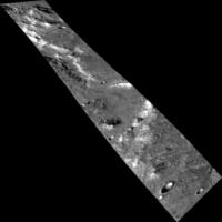
This warp command will warp the from cube (warp_from.cub) which is a
100Sx1000L image, to a 1000Sx1000L image and match the points from the
Control Points in warp_example1.net.
See the Control Network input file for more details.
This is the required input for the CNET parameter. In each control point there are
two measures. Measure 1 is the point on the from
cube you would
like to map to measure 2.
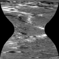
Output Image
Output image showing results of the warp application.
Output image for warp
Parameter Name:
TO
This is the output image for this example of warp.
The Control Network file link below contains the points required to
create this kind of a warp output.
This warp command will warp the from cube (warp_from.cub) which is a
100Sx1000L image, to a 1000Sx1000L image and match the points from the
Control Points in warp_example1.net.
See the Control Network input file for more details.
This is the required input for the CNET parameter. In each control
point there are two measures. Measure 1 is the point on the from
cube you would like to map to measure 2.
Output Image
Output image showing results of the warp application.
Output image for warp
Parameter Name:
TO
This is the output image for this example of warp.
The Control Network file link below contains the points required to
create this kind of a warp output.
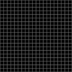
Example 3
Warp Grid Example 3
Description
This example shows the effect warm has on a grid. A 1000x1000 image
with grid lines every 50 pixels was created. The control net file has
4 points where the upper right and lower left corners were held. The
upper left and lower right points were move to 100,1 and 800,800,
respectively.
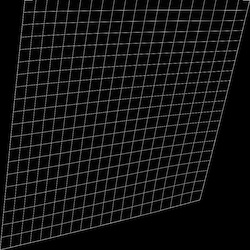
This warp command will warp the from cube (grid_raw.cub) which is a
1000Sx1000L image, to a 1000Sx1000L image and match the points from the
Control Points in warp_points.net. See the Control Network input file
for more details.
Input Image
Input image
Input image for warp
Parameter Name:
FROM
This input file is a 1000x1000 size image with grid lines at 50x50
increments.
This is the require input for the CNET parameter. In each control
point there are two measures. Measure 1 is the point on the from
cube you would like to map to measure 2.
Output Image
Output image showing results of the warp application.
Output image for warp
Parameter Name:
TO
This is the output image for this example of warp.
The Control Network file link below contains the points required to
create this kind of a warp output.