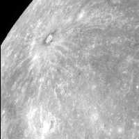
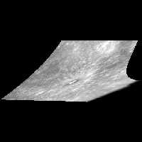
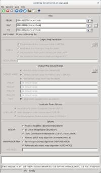
This program projects an ISIS
level0 or
level1
cube to a
map (ISIS
level2 cube).
The input cube requires
SPICE data and therefore
spiceinit should be executed prior to
running
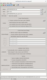
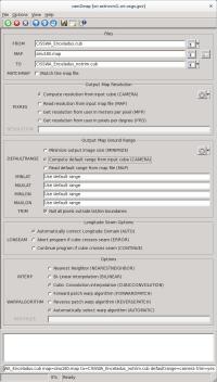
cam2map. The
map projection is defined using a
PVL file which is specified in
cam2map in the MAP parameter. Note: the system defaults
to the Sinusoidal projection (ISIS projection based templates are located in $ISISROOT/appdata/templates/maps).
To learn more about using map projections in ISIS, refer to the ISIS Workshop
"Learning About Map Projections".
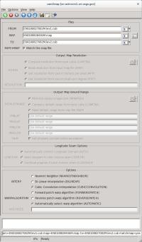
If you only entered the input cube (FROM) and output cube (TO) and changed no other parameters, the following
are the defaults for the Mapping group. Note: this is the PVL format you'll see in both the level2 ISIS cube header
and the MAP file:
  Group = Mapping
    TargetName             = "Obtained from the Instrument group"
    EquatorialRadius       = "Obtained from TargetAttitudeShape kernel"
    PolarRadius            = "Obtained from TargetAttitudeShape kernel"

    LatitudeType           = Planetocentric
    LongitudeDirection     = PositiveEast
    LongitudeDomain        = 360 (Could be automatically adjusted to 180 by LONSEAM)

    MinimumLatitude        = "Computed from the input camera cube"
    MaximumLatitude        = "Computed from the input camera cube"
    MinimumLongitude       = "Computed from the input camera cube"
    MaximumLongitude       = "Computed from the input camera cube"

    ProjectionName         = Sinusoidal
    CenterLongitude        = "Average of MinimumLongitude and MaximumLongitude"
    PixelResolution        = "Computed from the input camera cube"
  EndGroup
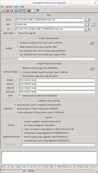
If you need to generate your own map file you can use the maptemplate program, or alternatively,
hand create a file using any text editor. The file need only specify the ProjectionName, as defaults will be
computed for the remaining map file parameters. The following table indicates how the defaults are
established:
| PARAMETER |
DEFAULT |
| TargetName |
Read from Instrument group in the input cube labels |
EquatorialRadius
PolarRadius |
Read from SPICE PCK file set during spiceinit. The PCK file is defined in the Kernels
group via the TargetAttitudeShape keyword |
| LatitudeType |
Planetocentric |
| LongitudeDirection |
PositiveEast |
| LongitudeDomain |
Normally 360 (0-360). However, if the 180 (-180,180) domain definition creates a smaller projected
cube, then use it instead. |
MinimumLatitude
MaximumLatitude
MinimumLongitude
MaximumLongitude |
Computed from the input cube or read from the map file. However, any combination of the
four values can then be overridden by the user. The values the user specifies are expected
to be in the coordinate system of the projection. |
PixelResolution
Scale |
Computed from the input cube or read from the map file. The value can be overridden by the user. |
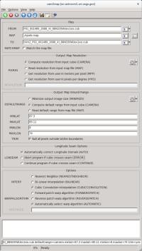
Alternatively, the map file can be an existing map projected (level2) cube. A level2 cube has PVL labels
and contains the Mapping group. Depending on the values of the input parameters, the output cube can
use some or all of the keyword values of the map file. For instance, setting MATCHMAP=yes causes all
of the mapping parameters to come from the map file, resulting in an output cube having the same
number of lines and samples as the map file.
If MATCHMAP=yes and the map file is missing a keyword like PixelResolution, the application will fail with
a PVL error. Setting MATCHMAP=no allows for some of the mapping components to be overridden by
the user or computed from the FROM cube.
If you are attempting to construct a mosaic, it is essential that the PixelResolution, EquatorialRadius,
PolarRadius, LatitudeType, LongitudeDirection, LongitudeDomain, ProjectionName, and projection specific
parameters (e.g., CenterLongitude, CenterLatitude) are the same for all cubes. That is, you should create
one map file and use it as input for all the cubes in your mosaic. Otherwise, the program will throw and error.
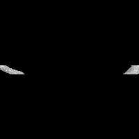
By letting the minimum and maximum latitude and longitude values default, the application will determine
the coverage of each image. However, if the mosaic Latitude and Longitude range are entered, each output
image will be projected to the full size of the mosaic resulting in large file sizes and images with many
NULL pixels. The following Mapping group could be used for mosaicking:
 Group = Mapping
   ProjectionName         = Sinusoidal
   CenterLongitude        = 0
   PixelResolution        = 100 <meters>
 EndGroup
Finally, depending on the projection, problems can occur with cubes that fall on the projection
longitude seam. For example, if you are making a mosaic with LongitudeDomain=360 and your
cube crosses 0/360 seam, the program will compute the default longitude range of the cube to
MinimumLongitude=0 and MaximumLongitude=360. A larger than necessary output image will be
created, with size inversely proportional to pixel resolution. The LONSEAM parameter allows you
to selectively handle this case. If you are making mosaics near the seam you will need to understand
and alter the default for this parameter.
Problems at the Longitude Seams of The ISIS Workshop "Learning About Map Projections" includes an example to help
illustrate the problem.
| Kay Edwards | 1986-09-02 |
Original version
|
| Jeff Anderson | 2003-05-02 |
Converted to Isis 3.0
|
| Jeff Anderson | 2003-06-05 |
Added to Camera category
|
| Stuart Sides | 2003-07-29 |
Modified filename parameters to be cube parameters where necessary
|
| Jeff Anderson | 2003-12-01 |
Reworked defaults for user parameters
|
| Jeff Anderson | 2004-01-21 |
Modified resolution parameters to eliminate inclusion/exclusion
dependences.
|
| Jeff Anderson | 2004-02-13 |
Added AUTOLON parameter
|
| Jeff Anderson | 2004-02-25 |
Fixed bug with ground range user option
|
| Elizabeth Miller | 2005-10-25 |
Added appTest
|
| Jacob Danton | 2005-12-02 |
Updated appTest
|
| Elizabeth Miller | 2006-03-23 |
Fixed appTest to reflect changes made in all camera models
|
| Tracie Sucharski | 2006-04-04 |
Check to see if center of input image projects, if it does, force the tile containing center
to be processed in ProcessRubberSheet.
|
| Jeff Anderson | 2006-04-04 |
Reworked user interface
|
| Elizabeth Miller | 2006-04-10 |
Reworked code for new user interface and added helper buttons
|
| Elizabeth Miller | 2006-05-18 |
Depricated CubeProjection and ProjectionManager to ProjectionFactory
|
| Elizabeth Miller | 2006-05-30 |
Moved Helper buttons and fixed error checking in helper methods
|
| Elizabeth Miller | 2006-09-06 |
Modified call to ProjectionFactory CreateForCube method to include a value of false
for the newly added sizeMatch parameter
|
| Jeff Anderson | 2006-12-06 |
Test to see if target is sky and abort
|
| Jeff Anderson | 2007-03-13 |
Add minimize option for DEFAULTRANGE
|
| Steven Lambright | 2007-06-22 |
Fixed typo and corrected XML
|
| Steven Lambright | 2007-08-22 |
Fixed lonseam option to work with minimize option correctly
|
| Stuart Sides | 2008-02-11 |
Fixed bug where the ground range was not pulled from the map file when
it was supposed to be (using DEFAULTRANGE = MAP).
|
| Christopher Austin | 2008-04-18 |
Added the MATCHMAP option.
|
| Steven Lambright | 2008-05-12 |
Removed references to CubeInfo
|
| Christopher Austin | 2008-07-15 |
Changed MATCHMAP to default off
|
| Steven Lambright | 2008-08-04 |
Changed MATCHMAP to have exclusions. If MATCHMAP is true, the PIXRES and DEFAULTRANGE
options can not be set. Changed the code to enforce MATCHMAP.
|
| Steven Lambright | 2008-09-10 |
Added the ability to change ProcessRubberSheet's tiling sizes. Now the Camera will decide upon the
tiling sizes used in ProcessRubberSheet, in order to fix problems found with the push frame cameras which
have small framelet sizes (less than 64 pixels tall). This is a passive ability with respect to the user;
no options or differences should be noticeable.
|
| Christopher Austin | 2008-10-31 |
Fixed DEFAULTRANGE > CAMERA option to accept MINLAT, MAXLAT, MINLON, and MAXLON
as overriding values.
|
| Christopher Austin | 2009-01-27 |
Fixed parameter names.
|
| Travis Addair | 2009-08-10 |
Mapping group parameters are now placed into the print file.
|
| Steven Lambright | 2011-01-31 |
Improved documentation
|
| Jai Rideout | 2011-02-10 |
Print file now includes PixelResolution, Scale, UpperLeftCornerX, and UpperLeftCornerY in Mapping group.
|
| Lynn Weller and Debbie A. Cook | 2012-01-17 |
Updated documentation text, added glossary links, and improved compatibility with Isis documentation.
|
| Jeff Anderson | 2012-04-30 |
Add forward and reverse patch rubbersheeting parameters.
|
| Debbie A. Cook | 2012-07-06 |
Updated Spice members to be more compliant with Isis coding standards. References #972.
|
| Debbie A. Cook | 2012-10-11 |
Updated to use new Target class. References Mantis ticket number #775 and #1114.
|
| Tracie Sucharski | 2012-12-06 |
Changed to use TProjection instead of Projection. References #775
|
| Kimbelry Oyama | 2013-07-11 |
Removed redundant checks for !ui.GetBoolean("MATCHMAP") from if statements. Added
ui.WasEntered before some of the parameters are used. Disabled LONSEAM when MATCHMAP
is selected. Fixes #1613.
|
| Jac Shinaman | 2016-01-29 |
Added new examples #5-8 describing the TRIM parameter. Fixes #0272.
|
| Jac Shinaman | 2016-02-09 |
Updated examples #1-4 GUI illustrations, and clarified some of the "Description" paragraphs.
Fixes #2389.
|
| Jac Shinaman | 2016-02-09 |
Brought code closer to ISIS coding standards. Added test to read NAIF body frame info from labels.
References #3934
|
| Curtis Rose | 2016-06-29 |
Fixed an error when matchmap was true, the user could attempt to add a mapping file
with a targetname that did not match the targetname of the instrument group of
the cube file. Fixes #1952.
|
| Adam Paquette | 2020-03-02 |
Added one last setImage call to check for pixel occlusion. Where any
pixel is occluded when the resulting latitude, or longitude differ from
the original latitude or longitude by 0.000001 degrees.
|
| Austin Sanders | 2020-03-02 |
Added an additional parameter (occlusion) to toggle occlusion processing.
|