ISIS Application Documentation
lronacecho | Printer Friendly View | TOC | Home |
Removes echo effects from a LRO NAC image
| Overview | Parameters | Example 1 |
Descriptionlronacecho implements a correction designed to remove an echo effect from LROC NAC images. In the summer of 2011, an echo effect was discovered in the NAC detectors. The signal in each pixel is replicated to a smaller extent in the pixel on the same line 2 columns over, 1 collumn in summed NACs. MSSS was consulted and it was confirmed this is a detector effect related to the high speed (>3000 lines/second) of the NAC detectors. The even and odd columns of the detector have separate signal processing chains, so when one pixel is read out, the next pixel with the same signal processing chain is two columns over. There is no measurable effect 4 columns over; the echo has no echo.
The size of the echo effect was determined by analyzing the signal at the edge the detector mask on each side of many NAC images, and by analyzing images with stars that had well-defined ghosts offset by two pixels. The effect is large enough that an inverse technique is needed to correct it with sufficient accuracy. The analysis determined that the echo is a larger percent of the signal for signals less than 100 DN. However, the correction uses a fixed fraction equal to
A brute force inverse technique derived from simple substitution was used early in the development of the echo correction. Let
So, we have the line of the actual image Note, however, that this equivalent to:
So we can calculate the new correction factors from the previously corrected pixels (the
In practice it has proven most successful to apply the echo correction after the flat field correction. CategoriesRelated Objects and DocumentsApplicationsHistory
|
Parameter GroupsFiles
Parameters
|
Files: FROM
Description
Use this parameter to select the cube to correct
| Type | cube |
|---|---|
| File Mode | input |
| Filter | *.cub |
Files: TO
Description
This file will contain the result of the correction
| Type | cube |
|---|---|
| File Mode | output |
| Pixel Type | real |
Parameters: DELTA
Description
This defines the multiplicative constant for the echo factor
| Type | double |
|---|---|
| Default | 0.326 |
Parameters: SMOOTHINGROWS
Description
This defines the number of detector samples in the begining of an image before the full correction is reached. Note that in summed images, this number of rows will be divided by two when translated to visible image space. That is: In native images, this parameter's default of 20 detector samples will affect the first 20 visible rows in image space. For summed images, this paramter's default of 20 detector samples will affect the first 10 visible rows in image space.
| Type | integer |
|---|---|
| Default | 20 |
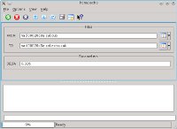
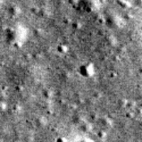
Example 1Removing echo from NACL (no summing) image Description
This example demonstrates the common usage of lronacecho. This is provided to help
demonstrate what noise is being affected and the expected results.
Command Line
lronacecho lronacecho from=nacl00020d3a.cal.cub to=nacl00020d3a.cal.echo.cub
Running lronacecho with default DELTA on a calibrated LRO NACL image
GUI Screenshot
Input Image
Output Images
|