

coreg
Subpixel registration of a pair of images
This program co-regsisters two images using an image-wide averaged sample/line translation with the TRANSLATE option or a set of variable sample/line translations with the WARP option. The program computes local translations spaced evenly throughout the image. The number and spacing of local translations is user defined. This allows for many output options including 1) directly creating the translated image, 2) creating a control network which can be used in other programs (e.g., translate, warp and qview-matchtool) or 3) creating a flat-field file usable in spreadsheets or plotting packages to visualize magnitude and direction of varying translations. For the TRANSLATE option, this implies that the internal geometry of both images be nearly the same so that the translation can be computed. That is, this program will not work if the translation varies significantly throughout the image. If condition of near constant translation is met then the translation can be computed to sub-pixel accuracy. If the internal geometry of both images do not match well, or a simple line/sample shift is not sufficient to register the images, the WARP option is a better choice than TRANSLATE because this uses the local translations to perform a rubber-sheet transformation. This option must be used with caution. It works very well with a well distributed collection of accurate control points across the image plane.
NOTE: While coreg uses a predefined autoreg parameter template, there are a variety of pattern matching algorithms and parameter settings that can be used to optimize the success and accuracy of the co-registration attempt with the control point measures. It is recommended that you review the Pattern Matching page from the "Related Objects and Documents" section below. It is essential for using this application to understand how to create a "registration template" file and how to size your search and pattern chips. We will continue with the discussion of functionality of this program assuming the reader has a fundamental knowledge of Automatic Registration. The user can also refer to the autoregtemplate application that offers a gui interface for creating an autoreg template file. Below we give an example of an autoreg parameter template file (DEFFILE):
      Object = AutoRegistration
        Group = Algorithm
          Name         = MaximumCorrelation
          Tolerance    = 0.7
        EndGroup

        Group = PatternChip
          Samples = 20
          Lines   = 20
          ValidMinimum = 1400
          ValidPercent = 75
        EndGroup

        Group = SearchChip
          Samples = 90
          Lines   = 90
          ValidMinimum = 1400
          ValidPercent = 75
        EndGroup
      EndObject
For further discussion of the parameters used in this DEFFILE, see the Pattern Matching document. Briefly, the example DEFFILE will allow a successful registration only where the MaximumCorrelation algorithm's goodness-of-fit result is >=0.7, pixel value is >1400, and at least 75% of the pixels in both the PatternChip or the SearchChip are valid pixels.
This program requires two input cubes, one which will be translated (FROM) and the other is held fixed (MATCH). The images must have the same number of samples and lines and can have only one band (use cube attributes to extract a single band if necessary). A grid will be defined across the held image using either the user parameters, ROWS and COLUMNS, or calculated based on the image size and the search chip size as follows: COLUMNS = (image samples - 1) / search chip samples + 1, and similarly for ROWS. Conceptually, the sparse grid defined by ROWS and COLUMNS will be laid on top of both images with even spacing between the rows (or columns) and but no row will touch the top or bottom of the image. That is, the grid is internal to the image.
At each grid intersection, the local translation will be computed. This is done by centering the search chip at the grid intersection for the image to be translated (FROM) and centering the pattern chip at the grid intersection for the held image (MATCH). The pattern chip is walked through the search chip to find the best registration (if any). Again, see the Pattern Matching document for further details. The local translation is recorded at all grid intersections that had a successful registration. The results are written to a control network and/or flat-file if requested. The average of the local translations is then used to compute an overall sub-pixel translation which can be applied to the FROM image and written as the output image (TO).
Some tips to improve odds of a successful registration are provided. In general a small pattern chip size makes registration more difficult. Depending on your dataset, 20x20 is probably a good starting point. The larger the translation, the larger the search chip size will need to be; if your translation is only a couple of pixels, you should make the search chip only slightly larger than the pattern (e.g., 25x25 vs 20x20). However if the translation is large you will need to expand the search area. For example, if the translation is roughly 45 pixels and your pattern is 20x20 the search area should be, roughly, 20+2*45 or 110x110.
The output control point network file (ONET) can be visually overlayed on the the displayed input images using the qview-MatchTool. The qview image display application will allow you to evaluate and interactively edit the network within the MatchTool.
Categories
Related Applications to Previous Versions of ISIS
This program replaces the following applications existing in previous versions of ISIS:- coreg2
- coregpr
- coregpr2
Related Objects and Documents
Applications
Documents
History
| Kris Becker | 2000-08-07 | Original Version. |
| Elizabeth Ribelin | 2005-08-25 | Ported to Isis3.0. |
| Elizabeth Miller | 2005-10-14 | Added warp option and fixed bug in control net creation. |
| Elizabeth Miller | 2006-03-23 | Fixed appTest. |
| Jacob Danton | 2006-01-06 | Fixed appTest to comply with changes made to the ControlMeasure class. |
| Jacob Danton | 2006-04-05 | Added error reporting when the registration was a failure. |
| Kris Becker | 2006-06-15 | Set the MATCH file as the reference image so it can be used in subsequent processing. Implemented use of unique serial numbers for each image. Issues still remain with handling band-to-band registrations within files. One alternative is to extract bands to separate files as a fallback approach is to use filenames as the serial number. This solution/alterntive is unique to coreg, however. |
| Brendan George | 2006-10-02 | Modified call for current time to point to Time class, instead of Application class. |
| Brendan George | 2006-12-08 | Modified to reflect changes to the SerialNumber class. |
| Steven Lambright | 2008-06-23 | Updated to properly check AutoReg::Register()'s return status. |
| Noah Hilt | 2008-08-13 | Added two new optional arguments to AutoReg: WindowSize and DistanceTolerance. These two arguments affect how AutoReg gathers and compares data for surface modeling and accuracy. Added more statistics to the Translation group, including min/max and standard deviation of line/sample changes. Added the AutoReg statistics to be displayed as well. |
| Travis Addair | 2009-08-10 | Auto registration parameters are now placed into the print file. |
| Eric Hyer | 2010-02-09 | Auto registration parameters now placed into the print file before potential throwing of exceptions. |
| Janet Barrett | 2010-07-30 | Changed REGDEF parameter name to DEFFILE. Changed CNETFILE parameter name to ONET. |
| Debbie A. Cook and Tracie Sucharski | 2011-06-07 | Changed point types "Ground" to "Fixed" and "Tie" to "Free". |
| Kris Becker | 2011-09-26 | Corrected parameter change to warp application (CONTROL is now CNET); added application test for parameter changes. |
| Kris Becker | 2011-10-07 | The documentation has been updated with review and contributions from Ella Lee, Chris Isbell and Moses Millazzo. |
| Travis Addair | 2012-01-26 | Added back GoodnessOfFit to Control Network and flatfile, mistakenly removed during binary Control Network conversion. |
| Tracie Sucharski | 2012-08-02 | Set networkId to Coreg in the output control network. |
| Tammy Becker | 2012-08-09 | Modified the documentation a bit and informed the user of the new qview-MatchTool that will now display the output network. |
| Kimberly Oyama | 2013-12-30 | Replaced the spaces in the point ID with underscores. References #1551. |
| Jeannie Backer | 2016-04-22 | Modified to use the FROM cube labels to set target instead of the TargetName. Updated the truth data for the cnet test. Added notarget test. References #3892 |
Parameters
Input Files
| Type | cube |
|---|---|
| File Mode | input |
| Filter | *.cub |
| Type | cube |
|---|---|
| File Mode | input |
| Filter | *.cub |
| Type | filename |
|---|---|
| File Mode | input |
| Default Path | $ISISROOT/appdata/templates/autoreg |
| Default | $ISISROOT/appdata/templates/autoreg/coreg.maxcor.p2020.s5050.def |
| Filter | *.def |
Output Cube
| Type | cube |
|---|---|
| File Mode | output |
| Internal Default | None |
| Filter | *.cub |
| Type | string | |||||||||
|---|---|---|---|---|---|---|---|---|---|---|
| Default | TRANSLATE | |||||||||
| Option List: |
|
| Type | integer |
|---|---|
| Default | 1 |
| Type | string | ||||||||||||
|---|---|---|---|---|---|---|---|---|---|---|---|---|---|
| Default | CUBICCONVOLUTION | ||||||||||||
| Option List: |
|
ControlNetOptions
| Type | filename |
|---|---|
| File Mode | output |
| Internal Default | None |
| Filter | *.net *.txt |
| Type | filename |
|---|---|
| File Mode | output |
| Internal Default | None |
| Filter | *.txt *.lis *.lst |
| Type | integer |
|---|---|
| Internal Default | Automatic |
| Minimum | 1 (inclusive) |
| Type | integer |
|---|---|
| Internal Default | Automatic |
| Minimum | 1 (inclusive) |
Example 1
Coregistration of 2 Images
Sample,Line,TranslatedSample,TranslatedLine,SampleDifference,LineDifference,GoodnessOfFit
211.875,164.283,200,133,-11.8751,-31.2829,0.991597
211.766,429.437,200,398,-11.7661,-31.4369,0.995987
The above text file is the ffile.txt file created when coreg is ran. The flat file is comma seperated
and can easily be imported into excel.
Command Line
coreg from=./lunar1.cub match=./lunar2.cub t=out.cub flatfile=ffile.txt
Input Images
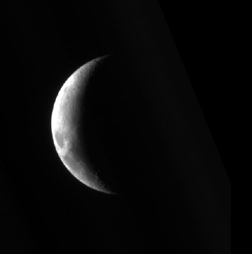
First Input image for coreg
First Input image
Parameter Name:
FROM
This is the 800 by 800 input image to be translated for the coreg example.
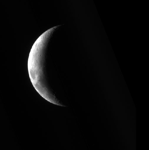
Second Input image for coreg
Second Input image
Parameter Name:
MATCH
This is the 800 by 800 input image to be held for the coreg example.
Output Image

Output image for coreg
Output image showing results of the coreg application.
Parameter Name:
TO
This is the 800 by 800 output image that results.