

pixel2map
Convert camera image to a map projection using a forward driven algorithm
In order for pixel2map to run successfully, input cubes must have SPICE data. The program spiceinit should be used to attach the appropriate SPICE data to input cubes. If a shape model is provided (or added in spiceinit by default), orthorectification is supported through the determination of the field-of-view (FOV) latitude/longitude coordinates as they map onto the digital elevation map (DEM). The pixel2map program also requires a map projection specification. The map projection is defined using a PVL file specified with the MAP parameter. The maptemplate program can be used to create a map projection file.
The cam2map program also projects a cube and is recommended for most mapping applications. The cam2map program assumes contiguous pixels and will interpolate to fill any gaps that occur in the output image during projection. The pixel2map program will preserve these gaps where the pixels are not contiguous. This program is designed to project cubes for the following cases:
- pixels do not overlap spatially
- data is smeared from long exposure times and drifting (see FOVRANGE=FULLEXPOSURE)
- data is captured from spectrometers
- CRISM
- DAWN VIR
- NEARS MSI
- VIMS
| pixel2map | cam2map |
| Uses a forward driven algorithm for projection. | Uses a reverse driven algorithm for projection. |
| Each input pixel is converted to a FOV polygon, typically using the latitude/longitude of the pixel corners, and rasterized into the output projected image by calculating output pixels that fall in the boundary of the input pixel. | Each input pixel is not converted to a polygon to be rasterized. Up to 16 input pixels are interpolated around the center latitude and longitude of the output map pixel. |
| The space between pixels is retained in the output projected cube. | The space between pixels are interpolated thus gaps are filled in the output projected cube. |
| The output cube will be spatially accurate for non-continuous pixels. | The output cube may not be spatially accurate as output pixels are interpolated. |
The examples below are Mars Reconnaissance Orbiter/CRISM cubes where scan lines do not overlap in their original state. The major difference is in the output of the application used to project the cube. Both applications will project the cube, but will also result in a different spatial outcome.
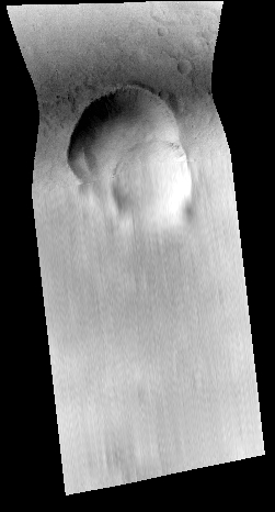
Left Cube: cam2map was chosen to project the cube. Notice the scan lines have been interpolated/filled. If you want to preserve gaps, cam2map will not achieve this result (but nearest-neighbor interpolation will be more accurate). In addition, the cube is no longer accurate (traceable for this type of instrument).
Right Cube: pixel2map was chosen to project the cube. Notice the gaps are retained in the output and the cube is spatially correct.
Mapping Parameterization
Several parameters of the map projection have default values when not specified in the map projection file. The default projection is the system sinusoidal projection. The following table indicates how the defaults are established:
| PARAMETER | DEFAULT |
| TargetName | Read from Instrument group in the input cube labels |
| EquatorialRadius
PolarRadius |
Read from SPICE PCK file set during spiceinit. The PCK file is defined in the Kernels group via the TargetAttitudeShape keyword |
| LatitudeType | Planetocentric |
| LongitudeDirection | PositiveEast |
| LongitudeDomain | Normally, 360. However, if the 180 domain causes less area to need to be projected then 180. |
| MinimumLatitude
MaximumLatitude MinimumLongitude MaximumLongitude |
Computed from the input cube or read from the map file. However, any combination of the four values can then be overridden by the user. The values the user specifies are expected to be in the coordinate system of the projection. |
| PixelResolution
Scale |
Computed from the input cube or read from the map file. The value can be overridden by the user. |
If you only entered the input cube (FROM) and output cube (TO) and changed no other parameters, the following is the default Mapping group:
  Group = Mapping
    TargetName             = Obtained from the Instrument group
    EquatorialRadius       = Obtained from TargetAttitudeShape kernel
    PolarRadius            = Obtained from TargetAttitudeShape kernel

    LatitudeType           = Planetocentric
    LongitudeDirection     = PositiveEast
    LongitudeDomain        = 360 (Could be automatically adjusted to 180 by LONSEAM)

    MinimumLatitude        = Computed from the input camera cube
    MaximumLatitude        = Computed from the input camera cube
    MinimumLongitude       = Computed from the input camera cube
    MaximumLongitude       = Computed from the input camera cube

    ProjectionName         = Sinusoidal
    CenterLongitude        = Average of MinimumLongitude and MaximumLongitude
    PixelResolution        = Computed from the input camera cube
  EndGroup
The map file can be an existing map projected (level2) cube. A level2 cube has PVL labels
with a Mapping group that is used to determine the default output map geometric extents and
resolution. Depending on the values of the input parameters, the output
cube can use some or all of the keyword values of the map file. For instance, setting
MATCHMAP=true causes all of the mapping parameters to come from the map file, resulting
in an output cube having the same number of lines and
samples as the map file. If MATCHMAP=true and the map file is missing
a keyword like PixelResolution, the application will fail with a PVL error. Setting
MATCHMAP=false allows for some of the mapping components to be overridden by the user or
computed from the FROM cube.
If you are attempting to construct a mosaic, it is important that the PixelResolution, EquatorialRadius, PolarRadius, LatitudeType, LongitudeDirection, LongitudeDomain, ProjectionName, and projection specific parameters (e.g., CenterLongitude, CenterLatitude) are the same for all cubes. That is, you should create one map file and use it as input for all the cubes in your mosaic. By letting the minimum and maximum latitude and longitude values default, the application will determine the coverage of each image. However, if the mosaic Latitude and Longitude range is entered, each output image will be projected to the full size of the mosaic resulting in large file sizes and images with many NULL pixels. The following Mapping group could be used for mosaicking:
 Group = Mapping
   ProjectionName         = Sinusoidal
   CenterLongitude        = 0
   PixelResolution        = 100 <meters>
 EndGroup
Finally, depending on the projection, problems can occur with cubes that fall on the projection longitude seam. For example, if you are making a mosaic with LongitudeDomain = 360 and your cube crosses the 0/360 seam, this program would compute the default longitude range of the cube to MinimumLongitude = 0 and MaximumLongitude = 360. A very large output image could be created depending on the pixel resolution. The LONSEAM parameter allows you to selectively handle this case. If you are making mosaics near the seam you will need to understand and alter the default for this parameter. Problems at the Longitude Seams of The ISIS Workshop "Learning About Map Projections" includes an example to help illustrate the problem.
Output of pixel2map
A single input file (FROM) produces a projected level2 cube. A list of files (FILELIST) produces an averaged mosaic as output. An additional count cube with one band that contains the number of input pixels averaged into each output pixel is created along with the output cube or mosaic.
Instantaneous FOV (IFOV) vs. Full FOV
As mentioned above, pixel2map uses a forward-driven mapping algorithm to create a projection. In short, this means that pixel2map determines a polygon (footprint) FOV for each input pixel and rasterizes it into the output image space. Depending on what the METHOD parameter has been set to, the input pixel DN value is included in the average of any output pixels that fall within the polygon.
The default behavior of pixel2map is FOVRANGE=INSTANTANEOUS. This means that the IFOV at the center time of the exposure is being used to determine each pixel's footprint. For spectrometers that have longer exposure times, this method does not adequately address any smearing that can occur due to drifting during the exposure. In order to account for smearing, FOVRANGE=FULLEXPOSURE can be used. This method determines a pixel's polygon by finding the IFOV polygons at the start time, middle time, and end time of the exposure and then drawing an envelope around these polygons. The images below visually demonstrate the differences between the two FOVRANGE parameter values.

For more details, see the parameter description for FOVRANGE or examples 3 and 4.
Categories
Related Applications to Previous Versions of ISIS
This program replaces the following application existing in previous versions of ISIS:- vims2map
History
| Stacy Alley | 2008-02-13 | Original version |
| Steven Lambright | 2008-05-13 | Removed references to CubeInfo |
| Christopher Austin | 2008-01-27 | Fixed parameter names |
| Tracie Sucharski | 2012-09-12 | Restored from revision 3911 and updated for revised IEXception, iString and FileName classes. |
| Debbie Cook | 2012-10-11 | Updated to use new Target class. References Mantis ticket #775 and #1114. |
| Tracie Sucharski, Stuart Sides | 2013-07-30 | Renamed from vims2map, generalized for all instruments, improved performance and accuracy. Fixes #1604. |
| Janet Richie, Ella Lee | 2013-11-21 | Updated documentation. |
| Sasha Brownsberger | 2015-01-19 | Updated function calls to reflect changes to ProcessGroundPolygons object. |
| Jeannie Backer | 2016-10-24 | Added feature to allow user to use full exposure duration to get polygons corresponding to real FOV. Improved coding standards. Fixes #4476. |
| Ian Humphrey | 2016-11-18 | Previous pixel2map was ignoring cube attributes when storing the FROM parameter internally. Running pixel2map now allows band selection on the FROM cube and FROMLIST cubes. Fixes #4520. |
| Ian Humphrey | 2016-11-30 | IsisCube labels and tables are now attached to the output cubes if there is a single input image. Fixes #4433. Removed unused UniveralGroundMap instance. References #4495. |
| Curtis Rose | 2016-12-09 | Added tests to for all errors. Fixed a check so now all files in a list have to have the same number of bands selected. References #4535. |
| Jesse Mapel | 2017-01-04 | Added the NUMIFOV parameter to determine how many IFOVs are used when creating a full FOV. References #4576. |
| Jesse Mapel | 2017-04-10 | Modified to no longer keep all cubes in the fromlist open. This resulted in crashing due to reaching the maximum number of open files when the fromlist was large. Cubes will now be opened one at a time and then closed before opening the next cube. Fixes #4761. |
| Ian Humphrey | 2017-05-23 | Updated documentation and added examples. Fixes #4537. |
| Alessandro Frigeri | 2024-08-22 | Added Vector output |
Parameters
Files
| Type | string | |||||||||
|---|---|---|---|---|---|---|---|---|---|---|
| Default | FROM | |||||||||
| Option List: |
|
| Type | cube |
|---|---|
| Exclusions |
|
| Filter | *.cub |
| Type | filename |
|---|---|
| File Mode | input |
| Exclusions |
|
| Filter | *.lis |
| Type | filename |
|---|---|
| File Mode | input |
| Default Path | $ISISROOT/appdata/templates/maps |
| Default | $ISISROOT/appdata/templates/maps/sinusoidal.map |
| Filter | *.map *.cub |
| Type | cube |
|---|---|
| File Mode | output |
| Pixel Type | real |
| Default | Null |
| Exclusions |
|
| Filter | *.cub |
| Type | filename |
|---|---|
| File Mode | output |
| Default | output.csv |
| Exclusions |
|
| Filter | *.csv |
Output Average
| Type | string | |||||||||
|---|---|---|---|---|---|---|---|---|---|---|
| Default | CENTER | |||||||||
| Option List: |
|
Output Map Resolution
| Type | string | |||||||||||||||
|---|---|---|---|---|---|---|---|---|---|---|---|---|---|---|---|---|
| Default | CAMERA | |||||||||||||||
| Option List: |
|
| Type | double |
|---|---|
| Minimum | 0.0 (exclusive) |
Output Map Ground Range
| Type | string | ||||||||||||
|---|---|---|---|---|---|---|---|---|---|---|---|---|---|
| Default | MINIMIZE | ||||||||||||
| Option List: |
|
| Type | double |
|---|---|
| Internal Default | Use default range |
| Minimum | -90.0 (inclusive) |
| Maximum | 90.0 (inclusive) |
| Type | double |
|---|---|
| Internal Default | Use default range |
| Minimum | -90.0 (inclusive) |
| Maximum | 90.0 (inclusive) |
| Greater Than | MINLAT |
| Type | double |
|---|---|
| Internal Default | Use default range |
| Type | double |
|---|---|
| Internal Default | Use default range |
| Greater Than | MINLON |
| Type | boolean |
|---|---|
| Default | FALSE |
| Type | string | |||||||||
|---|---|---|---|---|---|---|---|---|---|---|
| Default | INSTANTANEOUS | |||||||||
| Option List: |
|
| Type | integer |
|---|---|
| Default | 3 |
| Minimum | 3 (inclusive) |
Longitude Seam Options
| Type | string | ||||||||||||
|---|---|---|---|---|---|---|---|---|---|---|---|---|---|
| Default | AUTO | ||||||||||||
| Option List: |
|
Example 1
Default settings with MRO CRISM
Command Line
pixel2map
          from=crism.cub
          to=crism_default.cub
Input Image

CRISM input image
Input CRISM image
Parameter Name:
FROM
A CRISM image is being used for the input.
Output Images

Output projected image
Output projected image
Parameter Name:
TO
Project output image using default settings. Note the gaps in the projection.

Output count image
Output count imageThe count cube generated by pixel2map. Pixel values indicate how many input pixels were used to generate the average value for the respective output pixel.
Example 2
LONSEAM=CONTINUE with Cassini VIMS
Command Line
pixel2map
          from=C1621694254_1.ir.band248.cub
          map=$ISISROOT/appdata/templates/maps/equirectangular.map
          to=default.cub
          lonseam=continue
Input Image

Ingested VIMS-IR cube
Input VIMS-IR cube
Parameter Name:
FROM
A VIMS-IR cube ingested with vims2isis.
Output Image

Map projected VIMS-IR cube across the longitude seam
Output projected VIMS-IR cube
Parameter Name:
TO
The output cube is projected across the longitude seam. When using LONSEAM=CONTINUE, the output cube longitude domain will not be reset when the data crosses the longitude seam. For this image, a large gap of NULL pixels shows up in the output because the entire longitude range of the target body is included.
Example 3
Instantaneous FOV with Dawn VIR
Command Line
pixel2map
          from=VIR_IR_1B_1_506266095_refl_1.b75.l1.cub
          map=$ISISROOT/appdata/templates/maps/equirectangular.map
          to=dawn_vir_instantaneous_fov.cub
Input Image

Input image for pixel2map
Input image
Parameter Name:
FROM
This is the input DAWN VIR (IR) image for this example. Note the output "strips" and compare these with the output image in Example 4.
Output Image

Output image using FOVRANGE=INSTANTANEOUS
Output image FOVRANGE=INSTANTANEOUS
Parameter Name:
TO
This is the output image for the first run (FOVRANGE=INSTANTANEOUS).
Example 4
FULL FOV with Dawn VIR
Command Line
pixel2map
          from=VIR_IR_1B_1_506266095_refl_1.b75.l1.cub
          map=$ISISROOT/appdata/templates/maps/equirectangular.map
          to=dawn_vir_full_fov.cub
          fovrange=fullexposure
Input Image
Input image for pixel2map
Input image
Parameter Name:
FROM
This is the input DAWN VIR (IR) image for this example.
Output Image

Output image using FOVRANGE=FULLEXPOSURE
Output image FOVRANGE=FULLEXPOSURE
Parameter Name:
TO
This is the output image for FOVRANGE=FULLEXPOSURE. When comparing to the previous example, note that the output image data accommodates drift (the "strips" are wider).