

mdiscal
Calibrates MESSENGER/MIDS EDR/RDR products
- Step 1: Dark current correction
- Step 2: Linearity correction
- Step 3: Readout smear correction
- Step 4: Uniformity (flat field) correction
- Step 5: Absolute coefficient correction
- Step 6: Conversion to I over F
- Step 7: Empirical correction
Step 1: Dark current correction:
| Option | Description |
|---|---|
| None | No dark current correction is performed. |
| Standard | Messenger images have a strip of dark current data on the left-hand side. This will take a median of the first three sample columns (for unbinned data) and use it for the dark current on a line by line basis. |
| Linear | This will fit a line across the first column of data, which is dark current data, and use the line to determine the dark current correction. |
| Model | There are independent dark models, developed on-ground. This will use the most recent of these models to correct the dark current. |
There are times when the user selections for dark current correction will be rejected and altered by the program. In these cases a warning message will be printed to alert the user to the change. Below is an explanation of what happens in some special cases:
| DARKCURRENT parameter value | Valid dark pixels exist** | Exposure duration exceeds 1 second | Outcome |
|---|---|---|---|
| STANDARD | No | No | Dark current correction method is changed to MODEL. The program prints a warning message. |
| STANDARD | No | Yes | Dark current correction is turned off, but the rest of the calibration is performed. The program prints a warning message. |
| STANDARD | Yes | Yes or No | Dark current correction is performed with the original user input MODEL option. No warning message is needed. |
| LINEAR | No | No | Dark current correction method is changed to MODEL. The program prints a warning message. |
| LINEAR | No | Yes | Dark current correction is turned off, but the rest of the calibration is performed. The program prints a warning message. |
| LINEAR | Yes | Yes or No | Dark current correction is performed with the original user input MODEL option. No warning message is needed. |
| MODEL | Yes or No | No | Dark current correction is performed with the original user input MODEL option. No warning message is needed. |
| MODEL | No | Yes | Dark current correction is turned off, but the rest of the calibration is performed. The program prints a warning message. |
| MODEL | Yes | Yes | Dark current correction method is changed to STANDARD. The program prints a warning message. |
Step 2: Linearity correction:
Linearity measures the variability of a camera's DN level per unit exposure time and radiance, as a function of variation in exposure time or radiance. Using dark-corrected, desmeared DN values (DCDSI) taken from the center quarter of the images, response linearity was measured with both the NAC and WAC binned and not-binned.
Step 3: Smear correction:
Frame transfer smear corrections for MDIS follow the technique described for NEAR MSI image by Murchie et al. (1999). In brief, an image is exposed for a nominal integration time and is then transferred in 3.84 ms to a memory zone on the CCD, from which the analog signal is digitized line-by-line. Accumulation of signal continues during the finite duration of frame transfer, inducing a streak or frame-transfer smear in the wake of an illuminated object in the field of view, parallel to the direction of frame transfer. Note that the frame transfer occurs in the calibration pixels as well as on the imaging pixels. mdiscal accounts for the frame transfer smear contributed from the 16 calibration lines (removed from the PDS-archived images).
Step 4: Uniformity (flat field) correction:
Response uniformity, or flat field, is a measure of pixel-to-pixel variations in responsivity. Measurements of response uniformity of the WAC and NAC were conducted in the OCF, at room temperature and while cold, by imaging the integrating sphere with the two 45W bulbs illuminating the interior.
Step 5: Absolute coefficient correction:
This converts the DN values from responsivity to radiance values.
Step 6: Convert units to I over F:
This converts the DN values radiance values to I over F.
Step 7: Empirical correction:
Performs an empirical correction on the DN values by scaling them using the EmpiricalCorrectionFactor. Note this correction is only applied to WAC images.
Output units
The output units of the DNs will depend on which calibration flags are turned on.- If IOF=TRUE, output units are measured in I/F
- Otherwise if RADIOMETRIC=TRUE, output units are measured in W/(m**2 micrometer sr)
- If RADIOMETRIC=FALSE, output units are DNs
General calibration limitations
This program will throw an error and exit in the following circumstances:- The input cube is multiband.
- The input cube has less than 2 samples per line.
- The input cube is not unlutted.
- PixelBinningMode > 0 and unable to reduce.
MESSENGER MDIS calibration document excerpt
The following is an excerpt from the MESSENGER MDIS calibration document on this process
        USAGE
        =====

        Raw units are of DN converted to the physical units
        of radiance or I/F, following the calibration equation:

        L(x,y,f,T,t,b) = Lin[DN(x,y,f,T,t,b,MET) - Dk(x,y,T,t,b,MET) -
        Sm(x,y,t,b)] / {Flat(x,y,f,b) * t * [Resp(f,b,T)/Correct(f,MET)]}

        where:

        L(x,y,f,T,t,b) is radiance in units of W / (m**-2 microns**-1 sr**-1),
        measured by the pixel in column x, row y, through filter f, at CCD
        temperature T and exposure time t, for binning mode b,

        DN(x,y,f,T,t,b,MET) is the raw DN measured by the pixel in column x, row
        y, through filter f, at CCD temperature T and exposure time t, for binning
        mode b, and Mission Elapsed Time (MET),

        Dk(x,y,T,t,b,MET) is the dark level in a given pixel, derived from
        a model based on exposure time and CCD temperature,

        Sm(x,y,t,b) is the scene-dependent frame transfer smear for the pixel,

        Lin is a function that corrects small nonlinearity of detector response,

        Flat(x,y,f,b) is the non-uniformity or 'flat-field' correction,

        Resp(f,b,T) is the responsivity, relating dark-, flat-, and
        smear-corrected DN per unit exposure time to radiance,

        Correct(f,MET) is a time-variable correction to responsivity
        describing a sudden decrease in transmission of the WAC optics
        on 24 May 2011 and subsequent recovery to normal values,
        interpreted as due to contamination associated with MESSENGER's
        first periapse season over Mercury's hot pole and the subsequent
        bake-off of the contaminant,

        and

        t is the exposure time.

        The above equation assumes that data are in the native 12-bit format in
        which they were read off the CCD, and that onboard application of 12-to-8
        bit lookup tables (LUTs) has been inverted.

        This correction is done step-wise using the calibration tables and
        images in this directory as follows.


        (1) Inversion of 12 to 8 bit Compression
        ========================================

        8-to-12 bit inversion of DN values is required when the value of
        MESS:COMP12_8 is 1 (when the data are 8-bit). There are 8 inverse lookup
        tables (LUTs). The table to use is indicated by the value of MESS:COMP_ALG
        from 0 through 7. An 8-bit value (in a row of the table) is inverted by
        replacing it with the 12-bit value in the column corresponding to a
        particular LUT.

        The inversion tables are given in the product MDISLUTINV_0.


        (2) Subtraction of modeled dark level
        =====================================

        Two methods are used for subtraction of the dark level, one for
        exposure times greater than 1 sec and one for exposure times less than 1 sec.

        In the method for exposure times less than 1 sec, the DN values are valid
        columns in the masked 'dark strip' at the edge of the CCD are fitted
        linearly as a function of line in the image. Then the fits are subtracted
        from the pixels in each line of the CCD.

        In the method for exposure times greater than 1 sec, a model is used which accounts
        for variations in column (sample) in the image, which the previous
        method cannot do. However if the model were applied to longer exposures,
        it would yield larger residuals than the previous method.

        There are four separate models of dark level (dark current plus
        electronics bias), for the MDIS-WAC and MDIS-NAC (as indicated by the
        keyword INSTRUMENT_ID), and for each camera, without pixel binning turned
        on (MESS:FPU_BIN = 0) or with pixel binning turned on (MESS:FPU_BIN = 1).
        The models estimates the dark level Dk(x,y,t,T) as a function of column
        position x, row position y, exposure time t in milliseconds (as indicated
        by the keyword MESS:EXPOSURE or EXPOSURE_DURATION), and CCD temperature T
        (as indicated by the keyword MESS:CCD_TEMP):

        Dk(x,y,t,T) = C(T) + D(T) + [E(T) + F(T) * t] * y + {O(T) + P(T) * t +
         [Q(T) + S(T) * t] * y} * x

        Variables C(T), D(T), E(T), F(T), O(T), P(T), Q(T), and S(T) are all
        third-order functions of CCD temperature, for example:

        C(T) = H0 + H1 * T + H2 * T**2 + H3 * T**3

        In all cases x or y is in the range 0-1023 for a not-binned image (as
        indicated by the keyword MESS:FPU_BIN = 0) or 0-511 for a binned image (as
        indicated by the keyword MESS:FPU_BIN = 1). t is in units of milliseconds,
        and T is in UNCALIBRATED raw counts of CCD temperature.

        For each pixel in column x and row y of an image, application of the
        correction is:

        DN_dark(x,y,t,T) = DN(x,y,t,T) - Dk(x,y,t,T)

        where

        DN(x,y,t,T) is DN in 12-bit format,

        Dk(x,y,t,T) is the predicted DN level from the dark modeldark model, and

        DN_dark(x,y,t,T) is dark-corrected DN.

        The eight sets of coefficients for the WAC not-binned, WAC binned, NAC
        not-binned, and NAC binned dark models are given in the products
        MDISWAC_NOTBIN_DARKMODEL_0, MDISWAC_BINNED_DARKMODEL_0,
        MDISNAC_NOTBIN_DARKMODEL_0, and MDISNAC_BINNED_DARKMODEL_0 respectively.

        (3) Frame Transfer Smear Correction
        ===================================

        Accumulation of signal continues during the finite duration
        of frame transfer induces a streak or frame-transfer smear in the wake
        of an illuminated object in the field of view, parallel to the direction
        of frame transfer. This smear is approximated as:

        Sm(x,y,t,b,f) = SUMM(1,y-1) { t2/t * [DN_dark(x,y,t,b) -
        Sm(x,y,t,b,f)] / Flat(x,y,b,f)}

        where

        Sm(x,y,t,b,f) is the smear in column x and row y at exposure time t
        in binning mode b and filter f,

        Dk_dark (x,y,t,b) is dark-corrected DN in column x and row y at
        exposure time t and temperature T in binning mode b,

        Flat(x,y,b,f) is the flat-field correction in column x and row y in
        binning mode b and filter f,

        t is exposure time in milliseconds, and

        t2 is the time for frame transfer (about 3.4 ms) divided by the number of
        lines in the image in the direction of frame transfer, 1024 for
        full-frame images (when MESS:FPU_BIN = 0) or 512 for binned images (when
        MESS:FPU_BIN = 1).

        For each pixel in column x and row y of an image, application of the
        correction is :

        DN_dark_smear(x,y,t,b,f) = DN_dark(x,y,t,b,f) - Sm(x,y,t,b,f)

        where

        DN_dark_smear(x,y,t,b,f) is dark- and smear- corrected DN,

        DN_dark(x,y,t,b,f) is dark-corrected DN, and

        Sm(x,y,t,b,f) is the smear calculated as shown above.


        (4) Correction for CCD non-linearity
        ====================================

        To remove effects of nonlinearity in WAC image data, the following
        corrections should be applied after correction of dark current, bias,
        and smear.

        For DN_dark_smear > 1
        DN_lin = DN_dark_smear/[0.008760 * Ln(DN_dark_smear) + 0.936321]

        For DN_dark_smear less than or equal to 1
        DN_lin = DN_dark_smear/0.936321

        To remove effects of nonlinearity in NAC image data, the following
        procedure should be applied after correction of dark current, bias,
        and smear.

        For DN_dark_smear > 1
        DN_lin = DN_dark_smear/[0.011844 * Ln(DN_dark_smear) + 0.912031]

        For DN_dark_smear less than or equal to 1
        DN_lin = DN_dark_smear/0.912031

        where

        DN_dark_smear is the input dark- and smear-corrected DN, and

        DN_lin is linearized dark- and smear-corrected DN.


        (5) Flat-field correction
        =========================

        The flat field correction removes pixel to pixel differences in detector
        responsivity, so that the responsivity coefficients can be expressed as
        scalars for each filter. There is a separate flat-field image for MDIS-WAC
        and MDIS-NAC (as indicated by the keyword INSTRUMENT_ID), without pixel
        binning turned on (MESS:FPU_BIN = 0) or with pixel binning turned on
        (MESS:FPU_BIN = 1), for each separate filter (as indicated by the keyword
        FILTER_NUMBER). All of the files are in the 'FLAT' directory.

        For each pixel in column x and row y of an image, application of the
        correction is

        DN_flat(x,y,f,b) = DN_lin(x,y,f,b) / Flat(x,y,f,b)

        where

        DN_flat(x,y,f,b) is flat-fielded, linearized, dark- and smear-corrected
        DN,

        DN_lin(x,y,f,b) is linearized dark- and smear-corrected DN, and

        Flat(x,y,f,b) is the value in the appropriate flat-field image.


        (6) Conversion from DNs to radiance
        ===================================

        The value that relates corrected DN's measured per unit time to radiance
        is the responsivity. Responsivity is modeled as a function of which camera
        is being used (MDIS-WAC or MDIS-NAC as indicated by the keyword
        INSTRUMENT_ID), its binning state (as indicated by the keyword
        MESS:FPU_BIN), and in the case of the WAC the filter number (as indicated
        by the keyword FILTER_NUMBER). The coefficients used to calculate the
        responsivity are in the 'RESPONSIVITY' directory. For a camera, binning
        state, and filter, the responsivity is calculated from uncalibrated CCD
        temperature (as indicated by the keyword MESS:CCD_TEMP) as follows:

        Resp(f,T,b) = R(f,t=-30.3C,b) * [correction_offset(f,b) + T(CCD) *
        correction_coef1(f,b) + T(CCD)^2 * correction_coef2(f,b)]

        where

        Resp(f,T,b) is responsivity in filter f at CCD temperature T in binning
        state b,

        T(CCD) is raw CCD temperature in units of DNs,

        R(f,t=-30.3C,b) is responsivity in filter f in binning state b at CCD
        temperature of 1060 DN (-30.3C),

        correction_offset(f,b) is camera- and filter-dependent temperature
        correction offset for filter f and binning state b,

        correction_coef1(f,b) is the camera- and filter-dependent temperature
        correction first-order coefficient for filter f and binning state b.

        correction_coef2(f,b) is the camera- and filter-dependent temperature
        correction second-order coefficient for filter f and binning state b.

        To apply responsivity to obtain radiance L, the expression is

        L(f) = DN_flat(f) / (t * Resp(f,T,b) * Correct(f, MET))

        where

        L is radiance in units of W / (m**2 microns**1 sr**1),

        DN_flat is dark-, smear-, linearity-, and flat field-corrected DN,

        t is the exposure time in seconds,

        Resp(f,T,b) is the responsivity in filter f at CCD temperature T and
        binning state b, and

        Correct(f, MET) is the temporal correction to responsivity for
        filter f at time MET.


        (7) Conversion from radiance to I/F
        ===================================

        To convert from radiance to I/F (also known as radiance factor, the ratio
        of measured radiance to that which would be measured from a white
        perfectly Lambertian surface), the following expression should be applied:

        I_over_F(f) = L(f) * pi * (SOLAR_DISTANCE/149597870.691)**2 / F(f)

        where

        L(f) is calibrated radiance calculated as described above for some filter
        f,

        SOLAR_DISTANCE is that value for distance of the target object from the
        center of the sun in kilometers (as indicated by the keyword
        SOLAR_DISTANCE)

        149597870.691 is the number of kilometers in 1 AU

        F(f) is effective average solar irradiance sampled under the filter
        bandpass.

        The effective average solar radiance for each camera and bandpass is given
        in the SOLAR directory.
If run on a non-spiceinited cube, this program requires access to local mission-specific SPICE kernels, in order to find the distance between the sun and the target body. When run on a spiceinited cube, this can be determined using the camera model. Using a spiceinited cube as input has the advantage of not requiring that local mission-specific kernels be available. (See spiceinit web=true.)
Categories
Related Objects and Documents
Applications
History
| Steven Lambright | 2007-11-27 | Original version |
| Kris Becker | 2007-12-20 | Added computation of I/F reflectance for valid NAIF target bodies. |
| Kris Becker | 2008-01-19 | Corrected a bug that prevented the I/F correction from ever being applied. The exposure time must be expressed throughout as seconds and not milliseconds (engineering units) with the exception being the dark current model, which requires them to be in engineering units. There were incorrect values for the nominal filter wheel encoder values in the file $messenger/calibration/mdisCalibration.trn that incorrectly identified the filter. This has been corrected, but it was also determined that the validation of the proper filter wheel should take place in mdis2isis. Added loading of external file values as comma separated values (CSV) files. This includes the absolute response and solar irradiance constants. |
| Kris Becker | 2008-02-29 | Added filter dependant smear component support. These values are externally maintained in calibration/responsivity directory. |
| Steven Lambright | 2008-05-13 | Removed references to CubeInfo |
| Kris Becker | 2008-07-11 | The dark current model does not support exposure times greater than 2 seconds. In these cases, apply the STANDARD dark current processing and report this to the user as an error but complete processing. Users can always select a different model. |
| Kris Becker | 2008-09-03 | Corrected determination of dark column count; corrected computation of dark current correction based upon valid/good columns; added computation of dark strip mean after calibration as a sanity check on the process; updated ProductID and SourceProductId in the Archive group; Corrected units of resulting calibration; made filter characteristics of name, wavelength and width compliant with CDR SIS specifications; added program name and versions to RadiometricCalibration group; reworked how the dark model and flatfield are applied to support pixel binning. |
| Kris Becker | 2008-09-09 | Added additional tests for extreme observing conditions that do not allow the image to be calibrated. |
| Kris Becker | 2008-09-18 | Very minor change of watts unit expressed as W instead of w. |
| Kris Becker | 2008-11-19 | Changed the exposure threshold for the dark current model from 2 seconds to 1 second and it now uses the LINEAR model instead of the STANDARD model in this case; Implemented new quadratic responsivity equation for both WAC and NAC instruments that adds an additional term to the responsivity files; updated documentation. |
| Kris Becker | 2008-11-25 | Corrected inclusion of dark current model file to SourceProductId when applicable; bumped the version number to 3. |
| Mackenzie Boyd | 2009-09-03 | Added parameter to the usage of reduce to accommodate changes to reduce. |
| Mackenzie Boyd | 2011-02-04 | Fixed reduce parameters to use MODE instead of REDUCTION_TYPE. Fixed typo in docs. |
| Mackenzie Boyd | 2011-02-09 | Removed a cout, fixed calibration for images with nonzero pixel binning. |
| Kris Becker | 2011-04-20 | Added FLATFIELD and RADIOMETRIC parameters so that users can create several different products. When asking for dark columns to not be kept (KEEPDARK=FALSE), extra columns may be nulled as additional binning and compression introduces artifacts in adjacent columns; added new keyword (LeftSamplesNulled) to the RadiometricCalibration group indicating the number of NULLed columns. These changes result in version number 4 of the output calibration file. |
| Kris Becker | 2011-04-29 | Removed the From keyword from the RadiometricCalibration group created by this application. Added ValidDarkColumns to this group. This value indicates the number of samples used to compute the DarkStripMean. |
| Kris Becker | 2011-04-29 | Set the version back to 3 as it was deemed not neccessary to change the version after discussion with the MESSENGER team. |
| Kris Becker | 2012-10-23 | Several select calibration files were updated. New flat fields are MDISWAC_BINNED_FLAT_FIL03_5.cub, MDISWAC_NOTBIN_FLAT_FIL03_5.cub, MDISWAC_BINNED_FLAT_FIL06_5.cub and MDISWAC_NOTBIN_FLAT_FIL06_5.cub. Also updated was the frame transfer file MDISWAC_FRAME_TRANSFER_02.TAB. Added specific corrections for WAC images for a contamination event starting on May 24, 2011 through January 3, 2012 As a result, added new keywords to the RadiometricCalibration group to log this new correction. These keywords are: ContaminationEventFile, ContaminationEventDate and ContaminationEventFactor. Also corrected computation of dark strip average to properly report 0 when all these pixels are NULL pixels. Software version number is now 1.4. |
| Kris Becker | 2012-10-24 | Incremented the CDR version number from 3 to 4 per the request by the MESSENGER team. |
| Moses Milazzo | 2014-11-14 | Updated the smear correction to account for the 16 lines of calibration data that are not on the PDS images but still contribute to frame transfer smearing. Also updated the calibration tables (MDISWAC_FRAME_TRANSFER_??.TAB) with the correct frame transfer speed. Documentation was updated as well. Software version number is now 1.5. |
| Jeannie Backer | 2015-08-31 | Added ECFACTOR option so that the user can decide whether to apply the empirical correction factor. Changed label keywords in Radiometric Calibration group from ContaminationEvent to EmpiricalCorrection. Increased software version number to 1.6. Increased CDR version to 5. Made code more compliant with ISIS coding standards. Fixes #2332 |
| Jeannie Backer | 2015-09-15 | Modified code so that linearity, responsivity (absolute coefficient), and smear corrections are always performed. Previously these were only applied if the flat field correction was applied. This will change the output DNs for any images where FLATFIELD=false. Updated documentation. Fixes #2338 |
| Kristin Berry | 2021-02-26 | Updated to use camera for the target-sun distance and clock time to ET conversion, if possible. This enables the program to be run without local spice kernels (the spice server can be used for spiceinit.) |
Parameters
Files
| Type | cube |
|---|---|
| File Mode | input |
| Filter | *.cub |
| Type | cube |
|---|---|
| File Mode | output |
| Filter | *.cub |
Options
| Type | string | |||||||||||||||
|---|---|---|---|---|---|---|---|---|---|---|---|---|---|---|---|---|
| Default | MODEL | |||||||||||||||
| Option List: |
|
If this is selected, the dark current data are set to null in the output image.
Binning affects the number of columns that are determined to be set to null. Thus, KEEPDARK is overloaded in terms of any columns that contain artifacts that are generated by binning (or wavelet compression). These columns are set to null as well.
If no binning is applied, then four columns are set to null. If any combination of DPU or MP (essentially on-board processing) binning is applied, three columns will be set to null. When DPU and MP 2x2 binning occurs (essentially a 4x4 summing) three columns will be set to null. All other combinations of binning will have one column set to the null pixel value.
If KEEPDARK = TRUE, then no columns are set to null on output.
| Type | boolean |
|---|---|
| Default | false |
| Type | boolean |
|---|---|
| Default | True |
| Type | boolean |
|---|---|
| Default | True |
This option, when set, will convert the output to I/F from radiance values. To convert from radiance to I/F (also known as radiance factor, the ratio of measured radiance to that which would be measured from a white perfectly Lambertian surface), the following expression is applied:
I_over_F(f) = L(f) * PI * (SOLAR_DISTANCE/149597870.691)**2 / F(f)
where L(f) is calibrated radiance calculated for some filter f,
SOLAR_DISTANCE is that value for distance of the target object from
the center of the sun in kilometers (as indicated by the keyword
SOLAR_DISTANCE), 149597870.691 is the number of kilometers in 1 AU
and F(f) is effective average solar irradiance sampled under the
filter bandpass.
If the observed target is not of a valid body as recognized by NAIF, the output is left in radiance.
| Type | boolean |
|---|---|
| Default | True |
| Type | boolean |
|---|---|
| Default | True |
Example 1
Calibrating an MDIS image
Command Line
mdiscal FROM=EW0089565626A.cub
          TO=EW0089565626A.calib.cub DARKCURRENT=MODEL
GUI Screenshot
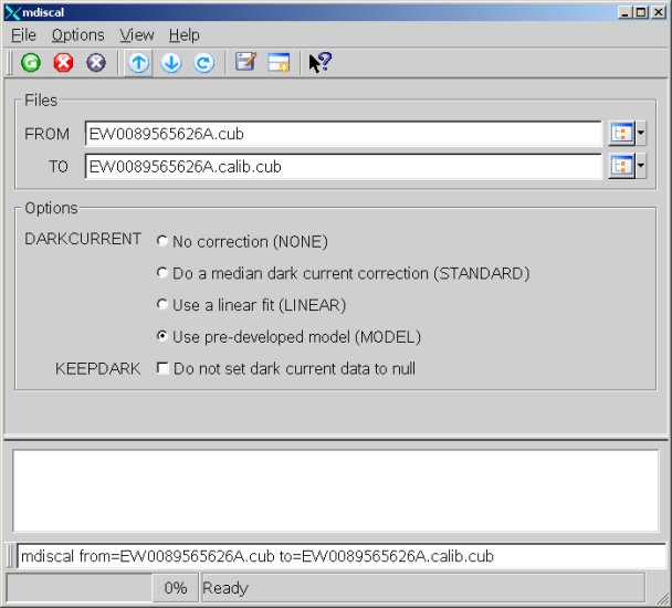
Calibrate an MDIS image
Calibrating EW0089565626A.cubThis is the GUI for mdiscal when converting the uncalibrated cube EW0089565626A.cub to the calibrated cube EW0089565626A.calib.cub.
Input Image
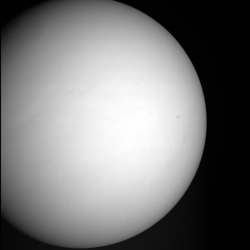
Input Cube
Input ImageThis is EW0089565626A.jpg before calibration.
Output Image
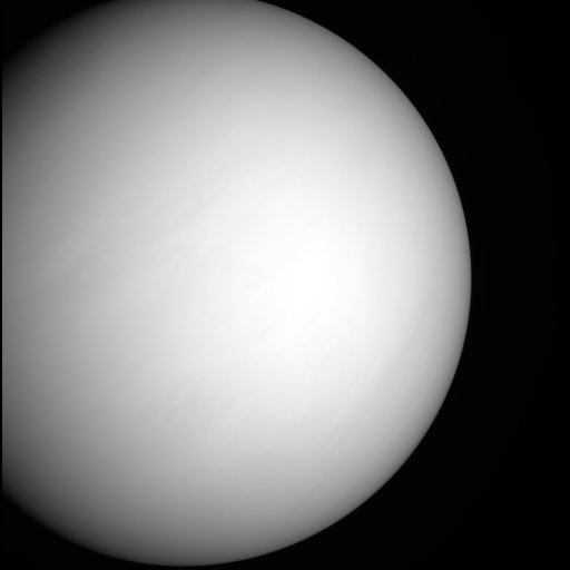
Output With Dark Model
Output Image With Dark ModelThis is the output generated by the default options.