

phocube
Create photometric and geometric information bands for an image cube
This program, phocube, creates backplane bands that contain photometric, geometric, and spacecraft instrument information for an image file. The parameter options range from photometric angles (incidence, emission, and phase) to various azimuth angles, and options based on spatial (latitude, longitude, and resolution) information. This program will not work on Level1 images without a camera model, or on mosaics. The input image pixels are not propagated to the output file unless the user selects the "DN" option. The following is a partial list of how users have made use of band output:
- Evaluate the individual bands in order to establish subsequent image processing steps
- Specify as input to other ISIS programs such as fx and photomet
- Demonstrate the result of each selected option
- Determine how the images are mosaicked together after the Level2 images are created from the Level1 images with backplanes
All ISIS applications default to the following geometric reference if a camera model exists:
- Longitude Domain = 360, longitude range reported from 0 to 360
- Latitude System = Ocentric
- Longitude Direction = East, longitude increases to the east
There are instances where the local emission angle and the local incidence angle will have values over 90 degrees. ISIS allows the computation of emission and incidence angles greater than 90 degrees. This feature allows representation of viewing and illumination conditions where there is actual target body surface data beyond the limb or deep terminator boundary areas. Applications such as photomet that applies photometric functions honor the 90-degree boundary. Applications such as photrim can be applied to the phocube output to replace the angle values above 90 degrees to NULL. There are certain processes that need these data, therefore it is allowed.
This program requires a Level1 file that has a successful "spiceinit" applied to it, or a Level2 image cube file. For every valid input pixel, an output pixel is computed based on either the SPICE information, or the map projected spatial information, or a pre-defined equation.
The parameters "morphologyRank" and "albedoRank" are specifically designed to be used by the ISIS mosaic programs. A mosaic program will automatically compare two pixel values to determine how each pixel is mosaicked into an output file, which depends on whether a morphology-based or an albedo-based product is desired. The program computes a DN value for every input pixel based on the formulas listed below and outputs the value to a backplane band. These backplane bands are used by the ISIS mosaic programs. The following are equations for "morphologyRank" and "albedoRank" options:
- MorphologyRank
- Equation = PixelResolution/cos(EmissionAngle)
- AlbedoRank
- Equation = PixelResolution * [(1/cos(EmissionAngle)) + (1/cos(IncidenceAngle))]
All the options in phocube are applicable if the input file is a Level1
image and has a camera model associated with the file. If the input file
is a map-projected Level2 image, only a few options are appropriate
and available for selection.
The following options are available for Level1 images that contain a camera model:
- DN
- EMISSION
- INCIDENCE
- PHASE
- OFFNADIRANGLE
- LOCALEMISSION
- LOCALINCIDENCE
- LATITUDE
- LONGITUDE
- DETECTORRESOLUTION
- OBLIQUEDETECTORRESOLUTION
- PIXELRESOLUTION
- LINERESOLUTION
- SAMPLERESOLUTION
- NORTHAZIMUTH
- SUNAZIMUTH
- SPACECRAFTAZIMUTH
- SUBSPACECRAFTGROUNDAZIMUTH
- SUBSOLARGROUNDAZIMUTH
- MORPHOLOGYRANK
- ALBEDORANK
- BODYFIXED
- RADEC (Right Ascension, Declination )
- LOCALTIME
- SUNILLUMINATIONMASK
- SURFACEOBLIQUEDETECTORRESOLUTION
- DN
- LATITUDE
- LONGITUDE
- PIXELRESOLUTION
The BandBin group keywords are updated in the labels of the output cube file. The keyword "Name" within the BandBin group, shown below, is populated with the name of each option selected by the user as bands. These bands can be referenced by their names in applications such as "mapmos" and "qview."
    Example:

    phocube from=EW0131773041G_cal.cub to=EW0131773041G_cal.pho.cub morph=true dn=true

    Sample of image label:

    Group = Dimensions
      Samples = 1024
      Lines   = 1024
      Bands   = 7
    End_Group

    Group = BandBin
      Name   = ("750 BW 5", "Phase Angle", "Emission Angle", "Incidence Angle",
          Latitude, Longitude, Morphology)
      Number = (7, 7, 7, 7, 7, 7, 7)
      Center = (748.7, 748.7, 748.7, 748.7, 748.7, 748.7, 748.7)
      Width  = (5.1, 5.1, 5.1, 5.1, 5.1, 5.1, 5.1)
    End_Group


    Note:  The first band retained the BandBin Name value from the input file.
    The program has "Phase Angle," "Emission Angle," "Incidence Angle,"
    "Latitude," and "Longitude" options pre-selected.
If the backplane bands generated by phocube are used in the mosaic programs and the mosaic requires the input image pixel, the "DN" parameter name must be set to "true" in phocube. When backplane bands are used in the "fx" or "photomet" program, it is not necessary to propagate the input image to the output file.
Categories
Related Applications to Previous Versions of ISIS
This program replaces the following applications existing in previous versions of ISIS:- lev1geoplane
- levgeoplane
- geoback
Related Objects and Documents
Applications
History
| Unknown | 1999-02-11 | Original version. |
| Stuart Sides | 2003-06-04 | Converted to ISIS3, and made it create a cube rather than adding backplanes. |
| Stuart Sides | 2003-07-29 | Modified filename parameters to be cube parameters where necessary. |
| Stuart Sides | 2005-09-09 | Fixed problem where the program threw an error when it tried to propagate the pixel type from the input file. |
| Stuart Sides | 2005-09-09 | Added the bandbin group to the cube labels. |
| Jeff Anderson | 2005-09-20 | Fixed a bug with switched samples and lines. |
| Elizabeth Miller | 2005-10-05 | Moved into Photometry and Radiometry category. |
| Elizabeth Miller | 2006-05-23 | Modified to use ProcessByBrick instead of ProcessByLine to make faster. |
| Brendan George | 2006-09-21 | Documentation fixes. |
| Steven Lambright | 2008-05-13 | Removed references to CubeInfo. |
| Steven Koechle | 2008-08-19 | Added new parameters: PIXELRESOLUTION, LINERESOLUTION, SAMPLERESOLUTION, DETECTORRESOLUTION, NORTHAZIMUTH, SUNAZIMUTH, SPACECRAFTAZIMUTH, OFFNADIRANGLE. |
| Steven Lambright | 2009-03-06 | Fixed a bug that occurred when processing band-dependent cubes. |
| Kris Becker | 2009-05-29 | Added the propagation of the input cube labels, objects, blobs, etc..., so the pedigree of the input source is retained. |
| Sharmila Prasad | 2009-07-17 | Set the defaults for PIXELRESOLUTION, LINERESOLUTION, SAMPLERESOLUTION, DETECTORRESOLUTION, NORTHAZIMUTH, SUNAZIMUTH, SPACECRAFTAZIMUTH, and OFFNADIRANGLE to FALSE. |
| Mackenzie Boyd | 2010-10-29 | Added parameters/bands SUBSPACECRAFTGROUNDAZIMUTH and SUBSOLARGROUNDAZIMUTH. |
| Travis Addair | 2011-02-10 | Added parameters LOCALINCIDENCE and LOCALEMISSION. |
| Kris Becker | 2011-08-08 | Added the option to propagate the input pixel value (DN) as the first band (however, this, by default, will not be invoked as default so as to preserve pre-existing behavior). Ensure the Center, OriginalBand, Name, and Width BandBin keyword values are populated properly and propagated to the output label (should support camera models). Added MORPHOLOGY and ALBEDO backplane options for special mosaic options. |
| Janet Barrett | 2012-02-22 | Added the capability to run this program on image files where the camera information is missing. The ability to generate lat/lon bands for image files is highly useful when performing fx operations on the files. Other bands that can be created for a mosaic file include: Dn and PixelResolution. A new parameter, SOURCE, was added so that the user can specify if their image does not contain a camera model. This will result in the appropriate parameter choices being greyed out. If the user does not specify that their file does not contain a camera model, then they will receive an error if they choose to create a band that cannot be created for the file. |
| Debbie A. Cook | 2012-07-06 | Updated Spice members to be more compliant with ISIS coding standards. References #972. |
| Ella Mae Lee | 2012-11-15 | Improved documentation, fixes #1254. |
| Tracie Sucharski | 2012-12-06 | Changed to use TProjection instead of Projection. References #775 |
| Tracie Sucharski | 2013-01-10 | Allow input cubes without the BandBin label group. Fixes #929. |
| Lynn Weller | 2013-02-25 | Removed links to applications imbedded in text and replaced with italicized application name. Added application links to the "Related Objects and Documents" section of the documentation. Fixes mantis ticket #1525. |
| Kimberly Oyama | 2013-11-20 | The error thrown when the input is a projected image was misleading. It has been fixed to be more helpful for the user. Fixes #923. |
| Makayla Shepherd | 2015-02-06 | Updated documentation. Fixes #1001. |
| Makayla Shepherd | 2015-07-02 | Added Ra/Dec and Body Fixed Coordinates options to help create new camera models and help with mission team operations. References #2277. |
| Tyler Wilson | 2016-08-17 | Added an ObliqueDetectorResolution band. This is an improvement over the previous DetectorResolution function (particularly for images taken near the limb of the target). References #476, #4100. |
| Kaj Williams | 2017-06-09 | Renamed albedo to albedoRank, and morph (or morphology) to morphRank (or MorphologyRank). Ref #4008. |
| Kaitlyn Lee | 2019-02-15 | Allowed RA and DEC to be exported regardless if the pixel is off body. Fixes #4446. |
| Kaitlyn Lee | 2020-06-04 | Added SPECIALPIXELS parameter to allow users to skip calculations on special pixels, excluding RA and DEC. This changed merged the two process functions, which were created to speed up the application when copying over DN values. After a few time tests, it doesn't look like the merge causes the application to run longer. Changed the process function to be a lambda function to get rid of global variables. |
| Kristin Berry | 2020-06-10 | Added the LOCALTIME parameter to output a band with the local solar time for each pixel. Fixes #3850 |
| Kaitlyn Lee | 2020-03-15 | Converted application and tests for Gtest conversion. |
| Stuart Sides | 2021-06-01 | Add ALLDNS parameter to propagate all input bands to the output instead of just one band. |
| Adam Paquette | 2020-08-23 | Added initial slope and backplane options for the local normal and the ellipsoid normal. |
| Ken Edmundson | 2024-04-24 | Added Sunilluminationmask and SurfaceObliqueDetectorResolution backplanes. SurfaceObliqueDetectorResolution is in addition to the existing ObliqueDetectorResolution. The difference is that ObliqueDetectorResolution uses the local emission angle while SurfaceObliqueDetectorResolution uses the emission angle calculated from the ellipsoid. Sunilluminationmask and SurfaceObliqueDetectorResolution were added to the U. of Arizona code base by the UA/OSIRIS-REx IPWG Team on 2018-09-19 and 2019-03-29 respectively. |
Parameters
Files
| Type | cube |
|---|---|
| File Mode | input |
| Filter | *.cub |
| Type | cube |
|---|---|
| File Mode | output |
| Pixel Type | real |
| Type | filename |
|---|---|
| File Mode | input |
| Internal Default | None |
| Filter | *.json |
| Type | string | |||||||||
|---|---|---|---|---|---|---|---|---|---|---|
| Default | CAMERA | |||||||||
| Option List: |
|
Photometry
| Type | boolean |
|---|---|
| Default | TRUE |
| Type | boolean |
|---|---|
| Default | FALSE |
If this parameter is true, all the DN values from all of the bands in the input image, subject to the input cube attribute, will be propagated to the output file. Calculations for the other bands that require a sensor model (e.g., phase) will be based on the first band, again subject to the cube attribute. This doesn't affect the values calculated for those bands when the input image bands are spatially aligned, but it is very import when the bands of the input image are not spatially aligned (e.g., Level 1, Odyssey, Themis IR). Use the input cube attribute to select the band used to calculate the other phocube values (e.g., ThemisIR.cub+9,1-5). The geometry of the first band or the first band in the input attribute, will be used to calculate the phocube values. NOTE: If the DN parameter is also set then ALLDNS will take precedence, and DN will be ignored.
| Type | boolean |
|---|---|
| Default | FALSE |
| Type | boolean |
|---|---|
| Default | TRUE |
| Type | boolean |
|---|---|
| Default | TRUE |
| Type | boolean |
|---|---|
| Default | TRUE |
| Type | boolean |
|---|---|
| Default | FALSE |
| Type | boolean |
|---|---|
| Default | FALSE |
| Type | boolean |
|---|---|
| Default | TRUE |
| Type | boolean |
|---|---|
| Default | TRUE |
| Type | boolean |
|---|---|
| Default | FALSE |
| Type | boolean |
|---|---|
| Default | FALSE |
| Type | boolean |
|---|---|
| Default | FALSE |
| Type | boolean |
|---|---|
| Default | FALSE |
| Type | boolean |
|---|---|
| Default | FALSE |
| Type | boolean |
|---|---|
| Default | FALSE |
| Type | boolean |
|---|---|
| Default | FALSE |
| Type | boolean |
|---|---|
| Default | FALSE |
| Type | boolean |
|---|---|
| Default | FALSE |
Note: The slope is measured relative to a sphere and not a more complex datum like the gravity model
If computing slopes, the input image must be a level1 image. To compute slopes for a level2 DEM use slpmap.| Type | boolean |
|---|---|
| Default | FALSE |
Note: These X, Y, and Z bands are in the body fixed reference frame.
| Type | boolean |
|---|---|
| Default | FALSE |
Note: These X, Y, and Z bands are in the body fixed reference frame.
| Type | boolean |
|---|---|
| Default | FALSE |
| Type | boolean |
|---|---|
| Default | FALSE |
| Type | boolean |
|---|---|
| Default | FALSE |
This band is computed from the pixel resolution
and emission angle using the following formula:
MorphologyRank = PixelResolution / cos(EmissionAngle)
The resulting output band can be used by automos to create a
morphology-based mosaic product. This option uses the
local emission angle if the input file
is initialized (spiceinit) with an elevation model (DEM); otherwise, it
uses the default calculation (from the ellipsoid). All computed cosines are
tested for zero. If the result is zero, then the value is set to a constant
value very close to zero.
- Append the following parameters to the automos command line to utilize this backplane band:
- priority=band type=keyword keyname=Name keyvalue=morphologyRank criteria=lesser.
| Type | boolean |
|---|---|
| Default | FALSE |
This band is computed from the pixel resolution,
incidence angle and emission angle
using the following formula:
AlbedoRank = PixelResolution * [(1 / cos(EmissionAngle)) + (1 / cos(IncidenceAngle))]
The resulting output band can be used by automos to create an albedo-based
mosaic product. This option always uses the
local emission angle and
local incidence angle if the input file
is initialized (spiceinit) with an elevation model (DEM); otherwise, it
uses the default calculation (from the ellipsoid). All computed cosines are
tested for zero. If the result is zero, then the value is set to a constant
value very close to zero.
- Append the following parameters to the automos command line to utilize this backplane band:
- priority=band type=keyword keyname=Name keyvalue=albedoRank criteria=lesser.
| Type | boolean |
|---|---|
| Default | FALSE |
| Type | boolean |
|---|---|
| Default | FALSE |
| Type | boolean |
|---|---|
| Default | FALSE |
| Type | boolean |
|---|---|
| Default | FALSE |
If this parameter is true, the Solar Illumination Mask (or shadow mask), will be determined for every pixel. This option is primarily useful for small irregular bodies (e.g. comets, asteroids), where terrain is occluded from solar illumination at the surface intersection point at a given pixel. This information cannot be provided solely by incidence or local incidence angles as the occlusion occurs due to foreground terrain, such as lobes in comets, at much larger distances than the proximity of the initial surface point of intersection. The output cube label will contain "Sun Illumination Mask" in the BandBin group, in band sequence of the output file.
The output mask pixel is a boolean value computed using ray trace functions. Pixels are either 1 (illuminated) or 0 (shadowed). A look direction from the sun is computed to the spacecraft (camera) pixel intercept location on the surface. If the solar intercept point on the surface is not the same point as seen from the spacecraft/camera perspective, it is deemed occluded (shadowed). For tessellated plate shape models, which are often used to represent the shape of irregular bodies, both camera and solar surface intercept points must occur on the same triangle at approximately the same location.
If the surface point is occluded/shadowed, a 0 (false) value is written as the output pixel mask value indicating it is not illuminated by the sun. All other cases will result in setting the output pixel mask value to 1 (true) indicating illumination by the sun. Note this mask will also include (i.e., identify pixels in) the local incidence backplane where the angles are greater than 90 degrees.
Note: The computation of this backplane is not supported for all ISIS shape models or for the ellipsoid. At this time we know that it functions properly using the Bullet ray trace engine.
| Type | boolean |
|---|---|
| Default | FALSE |
If this parameter is true, the Surface Oblique Detector Resolution will be computed for every pixel and placed in a band in the output cube. This value differs from the Oblique Detector Resolution due to use of the local emission angle for that data. It is computed using the emission angle computed from the ellipsoid, which will produce a smoother data plane. The output cube label will contain "Surface Oblique Detector Resolution" in the BandBin group, in band sequence of the output file. SurfaceObliqueDetectorResolution is in millimeters.
Note: The computation of this backplane is not supported for all ISIS shape models or for the ellipsoid. At this time we know that it functions properly using the Bullet ray trace engine.
| Type | boolean |
|---|---|
| Default | FALSE |
Example 1
Create latitude and morphologyRank backplane bands
Command Line
phocube
          from=EW0131773041G_cal.cub to=EW0131773041G_cal.pho.cub phase=no emission=no incidence=no
          longitude=no morphologyRank=yes
GUI Screenshot
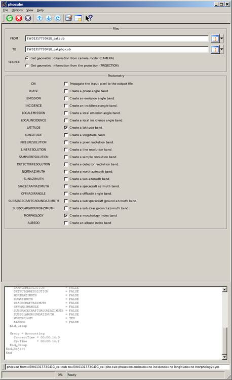
Example GUI
phocube GUI
Screenshot of GUI version of the application.
For this example,
only "LATITUDE" and "MORPHOLOGYRANK" are selected. The pre-selected
options "PHASE," "EMISSION," "INCIDENCE," and "LONGITUDE" are
deselected to avoid creating these unwanted backplanes.
Input Image
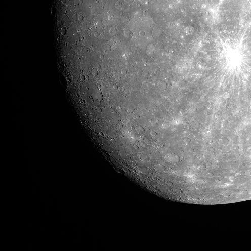
Input file
Input image
Parameter Name:
FROM
Screenshot of the input cube file.
Output Images
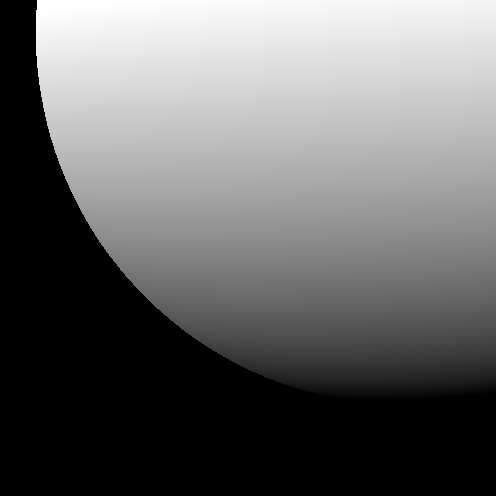
Output file band 1 (Latitude)
Output image band 1 (latitude)
Parameter Name:
TO
Screenshot of the first band in the output file. This file contains the latitude information with -72.2 degree as the minimum, and 6.27 degree as the maximum value.
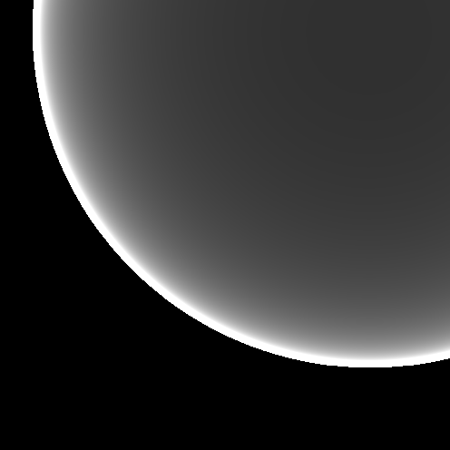
Output file band 2 (MorphologyRank)
Output image band 2 (morphologyRank)
Parameter Name:
TO
Screenshot of the second band in the output file. This file contains the computed morphologyRank values with 0.0 as the minimum, and 15.0 as the maximum value. The minimum and maximum values were manually selected to brighten the image for visual presentation. The actual range is between 2.8 and 41.5 DN values.
Example 2
Create "sun illumination mask" and "surface oblique detector resolution" backplane bands
Command Line
phocube
          from=20190425T211232S312_map_iofL2pan.cub to=20190425T211232S312_map_iofL2pan.pho.cub specialpixels=no
          phase=no emission=no incidence=no latitude=no longitude=no sunilluminationmask=yes
          surfaceobliquedetectorresolution=yes
GUI Screenshot
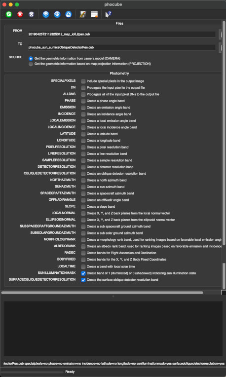
Example GUI
phocube GUI
Screenshot of GUI version of the application.
For this example,
only "SUNILLUMINATIONMASK" and "SURFACEOBLIQUEDETECTORRESOLUTION" are selected. The pre-selected
options "PHASE," "EMISSION," "INCIDENCE," "LATITUDE," and "LONGITUDE" are
deselected to avoid creating these unwanted backplanes.
Input Image
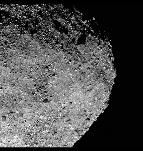
Input file
Input image
Parameter Name:
FROM
Screenshot of the input cube file.
Output Images
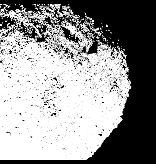
Output file band 1 (SunIlluminationMask)
Output image band 1 (Sun Illumination Mask)
Parameter Name:
TO
Screenshot of the first band in the output file. This band contains sun illumination information. Occluded and illuminated pixel values are 0 and 1 respectively.
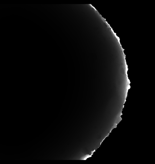
Output file band 2 (SurfaceObliqueDetectorResolution)
Output image band 2 (Surface Oblique Detector Resolution)
Parameter Name:
TO
Screenshot of the second band in the output file containing Surface Oblique Detector Resolution information computed using the emission angle determined from the ellipsoid. This produces a smoother data plane compared to that created with the Oblique Detector Resolution option, which is computed using the local emission angle from the shape model.