ISIS Application Documentation
cam2map | Standard View | TOC | Home |
Convert camera image to a map projection
Description
Categories
Groups
Examples
History
Description
If you only entered the input cube (FROM) and output cube (TO) and changed no other parameters, the following are the defaults for the Mapping group. Note: this is the PVL format you'll see in both the level2 ISIS cube header and the MAP file:
  Group = Mapping
    TargetName             = "Obtained from the Instrument group"
    EquatorialRadius       = "Obtained from TargetAttitudeShape kernel"
    PolarRadius            = "Obtained from TargetAttitudeShape kernel"

    LatitudeType           = Planetocentric
    LongitudeDirection     = PositiveEast
    LongitudeDomain        = 360 (Could be automatically adjusted to 180 by LONSEAM)

    MinimumLatitude        = "Computed from the input camera cube"
    MaximumLatitude        = "Computed from the input camera cube"
    MinimumLongitude       = "Computed from the input camera cube"
    MaximumLongitude       = "Computed from the input camera cube"

    ProjectionName         = Sinusoidal
    CenterLongitude        = "Average of MinimumLongitude and MaximumLongitude"
    PixelResolution        = "Computed from the input camera cube"
  EndGroup
If you need to generate your own map file you can use the maptemplate program, or alternatively, hand create a file using any text editor. The file need only specify the ProjectionName, as defaults will be computed for the remaining map file parameters. The following table indicates how the defaults are established:
| PARAMETER | DEFAULT |
| TargetName | Read from Instrument group in the input cube labels |
| EquatorialRadius
PolarRadius |
Read from SPICE PCK file set during spiceinit. The PCK file is defined in the Kernels group via the TargetAttitudeShape keyword |
| LatitudeType | Planetocentric |
| LongitudeDirection | PositiveEast |
| LongitudeDomain | Normally 360 (0-360). However, if the 180 (-180,180) domain definition creates a smaller projected cube, then use it instead. |
| MinimumLatitude
MaximumLatitude MinimumLongitude MaximumLongitude |
Computed from the input cube or read from the map file. However, any combination of the four values can then be overridden by the user. The values the user specifies are expected to be in the coordinate system of the projection. |
| PixelResolution
Scale |
Computed from the input cube or read from the map file. The value can be overridden by the user. |
Alternatively, the map file can be an existing map projected (level2) cube. A level2 cube has PVL labels and contains the Mapping group. Depending on the values of the input parameters, the output cube can use some or all of the keyword values of the map file. For instance, setting MATCHMAP=yes causes all of the mapping parameters to come from the map file, resulting in an output cube having the same number of lines and samples as the map file. If MATCHMAP=yes and the map file is missing a keyword like PixelResolution, the application will fail with a PVL error. Setting MATCHMAP=no allows for some of the mapping components to be overridden by the user or computed from the FROM cube.
If you are attempting to construct a mosaic, it is essential that the PixelResolution, EquatorialRadius, PolarRadius, LatitudeType, LongitudeDirection, LongitudeDomain, ProjectionName, and projection specific parameters (e.g., CenterLongitude, CenterLatitude) are the same for all cubes. That is, you should create one map file and use it as input for all the cubes in your mosaic. Otherwise, the program will throw and error.
By letting the minimum and maximum latitude and longitude values default, the application will determine the coverage of each image. However, if the mosaic Latitude and Longitude range are entered, each output image will be projected to the full size of the mosaic resulting in large file sizes and images with many NULL pixels. The following Mapping group could be used for mosaicking:
 Group = Mapping
   ProjectionName         = Sinusoidal
   CenterLongitude        = 0
   PixelResolution        = 100 <meters>
 EndGroup
Finally, depending on the projection, problems can occur with cubes that fall on the projection longitude seam. For example, if you are making a mosaic with LongitudeDomain=360 and your cube crosses 0/360 seam, the program will compute the default longitude range of the cube to MinimumLongitude=0 and MaximumLongitude=360. A larger than necessary output image will be created, with size inversely proportional to pixel resolution. The LONSEAM parameter allows you to selectively handle this case. If you are making mosaics near the seam you will need to understand and alter the default for this parameter. Problems at the Longitude Seams of The ISIS Workshop "Learning About Map Projections" includes an example to help illustrate the problem.
Categories
Related Applications to Previous Versions of ISIS
This program replaces the following applications existing in previous versions of ISIS:- lev1tolev2
- plansinu
- planorth
Parameter Groups
Files
| Name | Description |
|---|---|
| FROM | Input cube to project |
| MAP | File containing mapping parameters |
| TO | Newly mapped cube |
| MATCHMAP | Match the map file |
Output Map Resolution
| Name | Description |
|---|---|
| PIXRES | Defines how the pixel resolution in the output map file is obtained |
| RESOLUTION | Pixel resolution |
Output Map Ground Range
| Name | Description |
|---|---|
| DEFAULTRANGE | Defines how the default ground range is determined |
| MINLAT | Minimum Latitude |
| MAXLAT | Maximum Latitude |
| MINLON | Minimum Longitude |
| MAXLON | Maximum Longitude |
| TRIM | Set all pixels outside the bounding box to NULL |
Longitude Seam Options
| Name | Description |
|---|---|
| LONSEAM | How should images at the longitude seam be handled |
Options
| Name | Description |
|---|---|
| INTERP | Type of interpolation |
| WARPALGORITHM | Warp algorithm |
| PATCHSIZE | Patch size for forward or reverse warping |
| OCCLUSION | Detect and mark occluded pixels. |
Files: FROM
Description
The specification of the input cube to be projected. The cube must have been initialized using the spiceinit program.
| Type | cube |
|---|---|
| File Mode | input |
| Filter | *.cub |
Files: MAP
Description
A file containing the desired output mapping parameters in PVL format. This file can be a simple label file, or can be hand produced, or created via the maptemplate program. It can also be an existing cube or cube label which contains a Mapping group. In the latter case, the FROM cube will be transformed into the same map projection, resolution, etc.
| Type | filename |
|---|---|
| File Mode | input |
| Default Path | $ISISROOT/appdata/templates/maps |
| Default | $ISISROOT/appdata/templates/maps/sinusoidal.map |
| Filter | *.map *.cub |
Files: TO
Description
This file is the map projected (level2) image.
| Type | cube |
|---|---|
| File Mode | output |
| Filter | *.cub |
Files: MATCHMAP
Description
This forces all of the mapping parameters to come from the map file. Additionally, when the map file is an image the TO file will have the same number of lines and samples as the map file.
| Type | boolean |
|---|---|
| Default | false |
| Exclusions |
|
Output Map Resolution: PIXRES
Description
This parameter is used to specify how the pixel resolution is obtained for the output map projected cube.
| Type | string | |||||||||||||||
|---|---|---|---|---|---|---|---|---|---|---|---|---|---|---|---|---|
| Default | CAMERA | |||||||||||||||
| Option List: |
|
Output Map Resolution: RESOLUTION
Description
Specifies the resolution in either meters per pixel or pixels per degree
| Type | double |
|---|---|
| Minimum | 0.0 (exclusive) |
Output Map Ground Range: DEFAULTRANGE
Description
This parameter is used to specify how the default latitude/longitude ground range for the output map projected image is obtained. The ground range can be obtained from the camera or map file. Note the user can override the default using the MINLAT, MAXLAT, MINLON, MAXLON parameters. The purpose of the ground range is to define the coverage of the map projected image. Essentially, the ground range and pixel resolution are used to compute the size (samples and line) of the output image.
| Type | string | ||||||||||||
|---|---|---|---|---|---|---|---|---|---|---|---|---|---|
| Default | MINIMIZE | ||||||||||||
| Option List: |
|
Output Map Ground Range: MINLAT
Description
The minimum latitude of the output map. If this is entered by the user it will override the default camera or map value. By default, planetocentric latitudes are assumed unless the map file specifies otherwise.
| Type | double |
|---|---|
| Internal Default | Use default range |
| Minimum | -90.0 (inclusive) |
| Maximum | 90.0 (inclusive) |
Output Map Ground Range: MAXLAT
Description
The maximum latitude of the output map. If this is entered by the user it will override the default camera or map value. By default, planetocentric latitudes are assumed unless the map file specifies otherwise.
| Type | double |
|---|---|
| Internal Default | Use default range |
| Minimum | -90.0 (inclusive) |
| Maximum | 90.0 (inclusive) |
| Greater Than |
|
Output Map Ground Range: MINLON
Description
The minimum longitude of the output map. If this is entered by the user it will override the default camera or map value. By default, positive east longitudes in the range of 0 to 360 are assumed unless the map file specifies otherwise.
| Type | double |
|---|---|
| Internal Default | Use default range |
Output Map Ground Range: MAXLON
Description
The maximum longitude of the output map. If this is entered by the user it will override the default camera or map value. By default, positive east longitudes in the range of 0 to 360 are assumed unless the map file specifies otherwise.
| Type | double |
|---|---|
| Internal Default | Use default range |
| Greater Than |
|
Output Map Ground Range: TRIM
Description
The image is modified. The pixel dimensions of the file are retained; therefore, the number
of pixels is the same. However, the pixels that fall outside the default or specified latitude
and longitude range are set to NULL.
If camera is selected:
- You can opt to trim or not trim
- You can trim by entering the lat/lon range
- You cannot use the minimize parameter
- You can opt to trim or not trim
- You can trim by entering lat/lon range
- You cannot use the lonseam parameter
- You cannot use the minimize parameter
| Type | boolean |
|---|---|
| Default | FALSE |
Longitude Seam Options: LONSEAM
Description
With this option you can turn on/off the automatic longitude domain switching that occurs when a file crosses the boundary of the longitude domain (0-360 or -180 to 180). If the switching is turn off then you have the choice of making the program continue or exit when the cube does cross the boundary.
| Type | string | ||||||||||||
|---|---|---|---|---|---|---|---|---|---|---|---|---|---|
| Default | AUTO | ||||||||||||
| Option List: |
|
Options: INTERP
Description
This is the type of interpolation to be performed on the input.
| Type | string | ||||||||||||
|---|---|---|---|---|---|---|---|---|---|---|---|---|---|
| Default | CUBICCONVOLUTION | ||||||||||||
| Option List: |
|
Options: WARPALGORITHM
Description
This parameter is used to choose the warping algorithm, either the forward patch algorithm or the reverse patch algorithm. The default is to automatically choose the algorithm based on the input camera type (e.g., framing, linescan, pushframe).
| Type | string | ||||||||||||
|---|---|---|---|---|---|---|---|---|---|---|---|---|---|
| Default | AUTOMATIC | ||||||||||||
| Option List: |
|
Options: PATCHSIZE
Description
The forward and reverse patch algorithms try to fit an affine transform between the camera model coordinate and projection coordinate using the four corners of the patches. Patches that are too large may run faster at the risk of missing higher resolution information about the DTM. For example, a patch of 256x256 may have the same elevation at the four corners and center of the grid, but a crater may exist in one of the four quadrants of the patch. The crater, up to 128 pixels in diameter, may not be properly orthorectified. In general, small patch sizes are recommended (e.g., 4, 8).
| Type | integer |
|---|---|
| Minimum | 1 (inclusive) |
Options: OCCLUSION
Description
This parameter is used to toggle the occlusion detection algorithm.
If set true, then the occlusion detection algorithm locates and nullifies
occluded pixels. A pixel is determined to be occluded if the lat/lon
value of the pixel in projected image space does not match (within a
tolerance) the lat/lon value of the pixel in unprojected image space.
Highly dependent on DEM / image pixel resolution and accuracy of
coregistration between the two.
This parameter also significantly increases projection time. It is
recommended that this option is only used on images with known areas
of occlusion.
| Type | boolean |
|---|---|
| Default | false |
Examples
Example 1
Demonstrates the AUTO LONSEAM option
Description
Command Line
GUI Screenshot
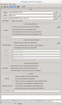
cam2map LONSEAM=AUTO GUI
|
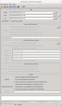
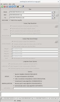
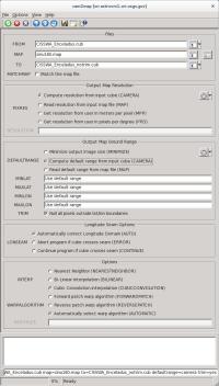
Example GUI
The top of the GUI shows the parameters filled in for input
files, output file, and output map resolution.
|
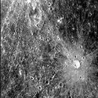
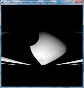
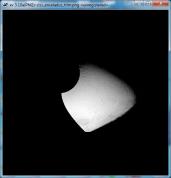
Input Image
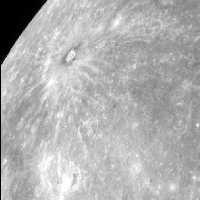
Input Messenger image
|
Input image for LONSEAM examples
Parameter Name:
FROM This is a Messenger narrow angle camera image. |
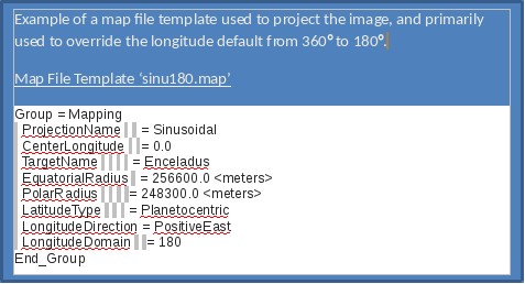
Data File
| Map file | Input map file defining the desired output map projection. This file is in PVL format. |
|---|
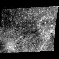
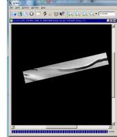
Output Image
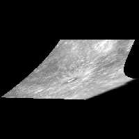
Output of cam2map run with LONSEAM=AUTO
|
Output image for cam2map LONSEAM=AUTO
Parameter Name:
TO This is the output of cam2map demonstrating LONSEAM set to AUTO. Contrast this output with the next example which was created with the LONSEAM set to CONTINUE. |
Example 2
Demonstrates the LONSEAM CONTINUE option
Description
Command Line
GUI Screenshot

cam2map LONSEAM=CONTINUE GUI
|
Example GUI
The top of the GUI shows parameters filled in for input
files, output file, and output map resolution.
|
Input Image
|
Input Messenger image
|
Input image for LONSEAM examples
Parameter Name:
FROM This is a Messenger narrow angle camera image. |
Data File
| Map file | Input map file defining the desired output map projection. This file is in PVL format. |
|---|
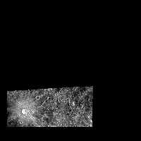
Output Image
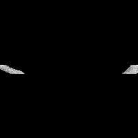
Output of cam2map run with LONSEAM=CONTINUE
|
Output image for cam2map LONSEAM=CONTINUE
Parameter Name:
TO This is the output of cam2map demonstrating LONSEAM set to CONT. Contrast this output with the previous example which was created with the LONSEAM set to AUTO. |
Example 3
Demonstrates one of two different ways to use MATCHMAP
Description
Command Line
GUI Screenshot
cam2map MATCHMAP GUI
|
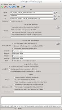
Example GUI
The top of the GUI reveals parameters filled in for input
files, output file, and output map resolution. Notice that with
MATCHMAP checked the remaining output map resolution parameters
are grayed out to show that they are no longer available for
input. All the mapping parameters will be read from the level 2
image entered for MAP.
|
Input Images
Input Messenger image
|
Input image for MATCHMAP examples
Parameter Name:
FROM This is a Messenger narrow angle camera image. |
Input level 2 image used for MAP
|
Input image for MATCHMAP examples
Parameter Name:
MAP This is a Messenger narrow angle camera image previously projected into an equirectangular map. |
Output Image
Output of cam2map run with MATCHMAP=YES and map file
|
Output image for cam2map LONSEAM=AUTO
Parameter Name:
TO This is the output of cam2map demonstrating the use of MATCHMAP=YES with an ISIS level 2 image as MAP. Contrast this output with the level 2 image used as MAP and with the next example which was also created with MATCHMAP=YES, but uses an ISIS map file as MAP. |
Example 4
Demonstrates a second way to use MATCHMAP
Description
Command Line
GUI Screenshot
cam2map MATCHMAP MAP GUI
|
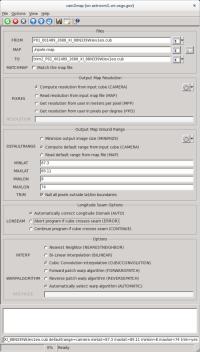
Example GUI
The top of the GUI illustrates parameters filled in for input
files, output file, and output map resolution. Notice that with
MATCHMAP checked the remaining output map resolution parameters
are grayed out to show that they are no longer available for
input. All the mapping parameters will be read from the map file.
The application will throw an error if any required information
is missing.
|
Input Image
|
Input Messenger image
|
Input image for MATCHMAP examples
Parameter Name:
FROM This is a Messenger narrow angle camera image. |
Data File
| Map file | Input map file defining the desired output map projection. This file is in PVL format. |
|---|
Output Image
|
Output of cam2map run with MATCHMAP=YES and map file
|
Output image for cam2map LONSEAM=AUTO
Parameter Name:
TO This is the output of cam2map demonstrating the use of MATCHMAP=YES with an Isis map file as MAP. Contrast this output with the previous example, which was also created with MATCHMAP=YES, but uses an Isis level 2 image for MAP. |
Example 5
The following four examples illustrate the effects of the TRIM option
Description
Command Line
GUI Screenshot
TRIM=NO GUI
|
Example GUI Screen shot of the entire GUI with parameters filled in for FROM file, TO file, default PIXRES, and Output Map Ground Range set to the CAMERA of the input cube. The rest of the parameters are all set to the defaults. |
Output Image
TRIM=NO output
|
Output image for cam2map TRIM=NO
Parameter Name:
TO This is the output of cam2map with TRIM turned off. |
Example 6
The following example illustrates what happens to the same data set with TRIM=YES
Description
Command Line
GUI Screenshot
TRIM=YES GUI
|
Example GUI Screen shot of the entire GUI with parameters filled in for FROM file, TO file, default PIXRES, Output Map Ground Range set to the CAMERA of the input cube, TRIM=YES, and MIN/MAX LAT/LON ranges are defined. The rest of the parameters are all set to the defaults. |
Output Image
TRIM=YES output
|
Output image for cam2map TRIM=YES
Parameter Name:
TO This is the output of cam2map with TRIM turned on. |
Example 7
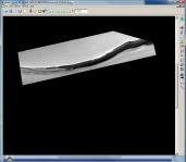
Potential anomalies using Sinusoidal projections
Description
Command Line
GUI Screenshot

TRIM=NO GUI
|
Example GUI Entire cam2map GUI with parameters filled in for FROM file, TO file, default PIXRES, and Output Map Ground Range set to the CAMERA of the input cube. The rest of the parameters are all set to the defaults. Note: the DEFAULT value for the TRIM parameter is NO, and therefore, it is not necessary to define TRIM. |
Data File
| Map file | Input map file defining the attributes of the desired output map projection. This file is in PVL format. |
|---|
Output Image
TRIM=NO output
|
Output image for cam2map TRIM=NO
Parameter Name:
TO This is the output of the cam2map Sinusoidal projection with TRIM turned off. |
Example 8
Solution for anomalies using Sinusoidal projections
Description
Command Line
GUI Screenshot
TRIM=YES GUI
|
Example GUI Entire cam2map GUI with parameters filled in for FROM file, TO file, default PIXRES, Output Map Ground Range set to the CAMERA of the input cube, and TRIM=YES. The rest of the parameters are all set to the defaults. |
Data File
| Map file | Input map file defining the attributes of the desired output map projection. This file is in PVL format. |
|---|
Output Image
TRIM=YES output
|
Output image for cam2map TRIM=YES
Parameter Name:
TO This is the output of the cam2map Sinusoidal projection with TRIM turned on. |
History
| Kay Edwards | 1986-09-02 | Original version |
| Jeff Anderson | 2003-05-02 | Converted to Isis 3.0 |
| Jeff Anderson | 2003-06-05 | Added to Camera category |
| Stuart Sides | 2003-07-29 | Modified filename parameters to be cube parameters where necessary |
| Jeff Anderson | 2003-12-01 | Reworked defaults for user parameters |
| Jeff Anderson | 2004-01-21 | Modified resolution parameters to eliminate inclusion/exclusion dependences. |
| Jeff Anderson | 2004-02-13 | Added AUTOLON parameter |
| Jeff Anderson | 2004-02-25 | Fixed bug with ground range user option |
| Elizabeth Miller | 2005-10-25 | Added appTest |
| Jacob Danton | 2005-12-02 | Updated appTest |
| Elizabeth Miller | 2006-03-23 | Fixed appTest to reflect changes made in all camera models |
| Tracie Sucharski | 2006-04-04 | Check to see if center of input image projects, if it does, force the tile containing center to be processed in ProcessRubberSheet. |
| Jeff Anderson | 2006-04-04 | Reworked user interface |
| Elizabeth Miller | 2006-04-10 | Reworked code for new user interface and added helper buttons |
| Elizabeth Miller | 2006-05-18 | Depricated CubeProjection and ProjectionManager to ProjectionFactory |
| Elizabeth Miller | 2006-05-30 | Moved Helper buttons and fixed error checking in helper methods |
| Elizabeth Miller | 2006-09-06 | Modified call to ProjectionFactory CreateForCube method to include a value of false for the newly added sizeMatch parameter |
| Jeff Anderson | 2006-12-06 | Test to see if target is sky and abort |
| Jeff Anderson | 2007-03-13 | Add minimize option for DEFAULTRANGE |
| Steven Lambright | 2007-06-22 | Fixed typo and corrected XML |
| Steven Lambright | 2007-08-22 | Fixed lonseam option to work with minimize option correctly |
| Stuart Sides | 2008-02-11 | Fixed bug where the ground range was not pulled from the map file when it was supposed to be (using DEFAULTRANGE = MAP). |
| Christopher Austin | 2008-04-18 | Added the MATCHMAP option. |
| Steven Lambright | 2008-05-12 | Removed references to CubeInfo |
| Christopher Austin | 2008-07-15 | Changed MATCHMAP to default off |
| Steven Lambright | 2008-08-04 | Changed MATCHMAP to have exclusions. If MATCHMAP is true, the PIXRES and DEFAULTRANGE options can not be set. Changed the code to enforce MATCHMAP. |
| Steven Lambright | 2008-09-10 | Added the ability to change ProcessRubberSheet's tiling sizes. Now the Camera will decide upon the tiling sizes used in ProcessRubberSheet, in order to fix problems found with the push frame cameras which have small framelet sizes (less than 64 pixels tall). This is a passive ability with respect to the user; no options or differences should be noticeable. |
| Christopher Austin | 2008-10-31 | Fixed DEFAULTRANGE > CAMERA option to accept MINLAT, MAXLAT, MINLON, and MAXLON as overriding values. |
| Christopher Austin | 2009-01-27 | Fixed parameter names. |
| Travis Addair | 2009-08-10 | Mapping group parameters are now placed into the print file. |
| Steven Lambright | 2011-01-31 | Improved documentation |
| Jai Rideout | 2011-02-10 | Print file now includes PixelResolution, Scale, UpperLeftCornerX, and UpperLeftCornerY in Mapping group. |
| Lynn Weller and Debbie A. Cook | 2012-01-17 | Updated documentation text, added glossary links, and improved compatibility with Isis documentation. |
| Jeff Anderson | 2012-04-30 | Add forward and reverse patch rubbersheeting parameters. |
| Debbie A. Cook | 2012-07-06 | Updated Spice members to be more compliant with Isis coding standards. References #972. |
| Debbie A. Cook | 2012-10-11 | Updated to use new Target class. References Mantis ticket number #775 and #1114. |
| Tracie Sucharski | 2012-12-06 | Changed to use TProjection instead of Projection. References #775 |
| Kimbelry Oyama | 2013-07-11 | Removed redundant checks for !ui.GetBoolean("MATCHMAP") from if statements. Added ui.WasEntered before some of the parameters are used. Disabled LONSEAM when MATCHMAP is selected. Fixes #1613. |
| Jac Shinaman | 2016-01-29 | Added new examples #5-8 describing the TRIM parameter. Fixes #0272. |
| Jac Shinaman | 2016-02-09 | Updated examples #1-4 GUI illustrations, and clarified some of the "Description" paragraphs. Fixes #2389. |
| Jac Shinaman | 2016-02-09 | Brought code closer to ISIS coding standards. Added test to read NAIF body frame info from labels. References #3934 |
| Curtis Rose | 2016-06-29 | Fixed an error when matchmap was true, the user could attempt to add a mapping file with a targetname that did not match the targetname of the instrument group of the cube file. Fixes #1952. |
| Adam Paquette | 2020-03-02 | Added one last setImage call to check for pixel occlusion. Where any pixel is occluded when the resulting latitude, or longitude differ from the original latitude or longitude by 0.000001 degrees. |
| Austin Sanders | 2020-03-02 | Added an additional parameter (occlusion) to toggle occlusion processing. |