ISIS Application Documentation
higlob | Standard View | TOC | Home |
Combines HiRISE image data with all pixel data in the blobs
Description
Categories
Groups
History
Description
This program will create a new image with the calibration pixel data at the top, followed by the main image data. Both the calibration and main image will have the buffer pixels added to the left side and the dark pixels to the right side.
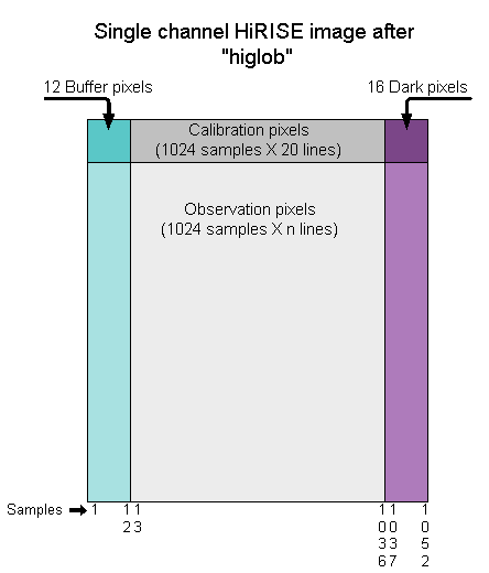
The pixel values are retrieved from either the Isis tables or the main image. The calibration buffer and dark pixels are pulled from the "HiRISE Ancillary" table. The main calibration image pixels come from the "HiRISE Calibration Image" table. The image buffer and dark pixels come from the "HiRISE Ancillary" table. The observation pixels come from the main Isis cube.
The calibration image and observation image pixels of a HiRISE image can be flipped from left to right using the "FLIP" parameter. See the "FLIP" parameter description for details.
Categories
Parameter Groups
Files
| Name | Description |
|---|---|
| FROM | Input HiRISE cube |
| TO | Combined output cube |
Options
| Name | Description |
|---|---|
| FLIP | Specify HiRISE channel (0 or 1) image & calibration image to flip |
Files: FROM
Description
The HiRISE cube containing the image and tables from the EDR product. This must be an Isis cube (i.e., "hi2isis" must be run before "higlob").
| Type | cube |
|---|---|
| File Mode | input |
| Filter | *.cub |
Files: TO
Description
The output cube containing the main image data, calibration data, buffer pixels and dark pixels.
| Type | cube |
|---|---|
| File Mode | output |
| Filter | *.cub |
Options: FLIP
Description
This is typically channel 1 (discovered after launch!) rather than 0, but this option allows you to choose the channel you want to flip. The default (1) is the one designated as the channel to flip to best assist in calibration analysis.
If FLIP matches the value of the ChannelNumber keyword in the Instrument group, then both the observation and calibration image data will be filpped left to right. This does not modify the byte order of the individual pixels, and does not flip any of the buffer or dark pixels.
To ensure that you flip no channel, set FLIP to "None".
| Type | string | ||||||||||||
|---|---|---|---|---|---|---|---|---|---|---|---|---|---|
| Default | 1 | ||||||||||||
| Option List: |
|
History
| Stuart Sides | 2004-10-06 | Original version |
| Stuart Sides | 2005-06-07 | Fixed problem with special pixels in image ancillary, calibration and calibration ancillary areas. They are now converted to double precision special pixels before being inserted into the Buffer. |
| Stuart Sides | 2005-07-21 | Fixed another problem with special pixels in the image ancillary table. The 16 bit integer special pixel values in table were not being converted to double special pixels when being dumped into the output buffer. |
| Kris Becker | 2005-09-23 | During our first observation in cruise, it was determined that channel 1 required flippping rather than channel 0. This confusion due to assumptions of which channel, 0 or 1, was on the left or right side of the CCD. Channel 1 is on the left, channel 0 on the right. Also changed the FLIP parameter to an integer to allow the user to choose either channel to flip (so we don't have to do this again!) |
| Stuart Sides | 2006-09-19 | Fixed a memory leak caused by not deleting a global pointer. |
| Brendan George | 2006-09-28 | Documentation fixes |
| Steven Lambright | 2008-05-13 | Removed references to CubeInfo |
| Jeannie Backer | 2012-10-04 | PROG: Changed references to TableField methods to lower camel case. Ordered includes. Added g_ prefix to global variables. References #1169. |