The jigsaw application performs a bundle adjustment on a group of overlapping Isis,
level 1, cubes from framing and/or line-scan cameras. The adjustment
simultaneously defines the selected image geometry information (camera pointing, spacecraft
position) and control point coordinates (x,y,z or lat,lon,radius) to reduce
boundary mismatches in mosaics of the images.
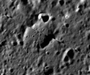
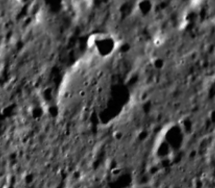
This functionality is demonstrated below in a zoomed-in area of a mosaic of a
pair of overlapping Messenger images. In the before jigsaw mosaic on the left
(uncontrolled), the features on the edges of the images do not match. In the after
jigsaw mosaic on the right (controlled), the crater edges meet correctly and the
seam between the two images is no longer visible.
The jigsaw application assumes spiceinit has been run on the input cubes so that
SPICE is included in the Isis cube labels in the Kernels group. In order to
run the program, the user must provide a list of input cubes, an input control
net, the name of an output control net, and the adjustment parameters.
jigsaw outputs a new control net that includes the initial state of the
points in the network and their final state after the adjustment. The initial states of
the points are tagged as a priori in the control net, and their final
states are tagged as adjusted. The measured sample/line positions
associated with the control points in the net are not changed. SPICE
in the cube labels is updated at the end of the adjustment only
if the bundle converges and the UPDATE parameter is selected.
Optional output files can be selected to provide more information for analyzing the
results. BUNDLEOUT_TXT provides an overall summary of the bundle adjustment.
It lists the user input parameters selected and tables of statistics for both the
images and the points. The image statistics can also be written to a separate
CSV file and likewise for the point statistics with the OUTPUT_CSV
option selected. RESIDUALS_CSV provides a table of the measured image
coordinates and the final sample, line, and overall residuals
in both millimeters and pixels.
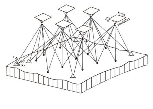
The functional model for the bundle adjustment is the collinearity
condition. It stipulates that the camera perspective center, a ground
point, and its associated image point measurement be collinear. The diagram
below demonstrates the collinear condition in a bundle adjustment.
The vectors formed by connecting each object space point (target surface x,y,z)
and its corresponding image space points (sample,line) form
a bundle of light rays.
Kraus, Karl., 1993. Photogrammetry Vol. I., Fundamentals and Standard
Processes, Der. Dümmler Verlag, Bonn, Germany, ISBN 3-427-78684-6, 397
pages.
Relevant Documentation
For information on what the original jigsaw code was based on checkout
Rand Notebook
Known Issues
Running jigsaw with a control net containing JigsawRejected
flags may result in bundle failure
When running jigsaw with Outlier Rejection turned on,
control points and/or control measures may be flagged as
JigsawRejected in the output control net file. If this output net
file is then used in a subsequent jigsaw run, these points and
measures will be erroneously ignored, potentially causing the bundle
adjustment to fail.
--Workarounds
Run jigsaw with Outlier Rejectionoff.
Do not use the output control net file in subsequent jigsaw runs.
Convert the output control net file from binary to PVL and back using
cnetbin2pvl and cnetpvl2bin. This will
clear the JigsawRejected flags.
Solving for the target body radii (triaxial or mean) is NOT possible and
likely increases error in the solve.
With the current jigsaw implementation, it is NOT possible to individually
solve for either the mean or triaxial radii as seperate calculations in
the bundle adjustment. More specifically, the target body radii has no
effect when solving for individual points and thus cannot be solved for in the bundle.
A local radii solve is already part of the sequence of equations that jigsaw
uses to compute various partial derivatives to populate the solve matrix.
A seperate mean or triaxial radii solve can be applied to the target body
and the partials from this separate application are added to the
solve matrix. This option adds additional computation time to jigsaw
and creates additional uncertainty/error in the bundle adjust. We advise
the mean and triaxial radii solve be avoided.
If you are trying to generate a spheroid from a control network there are
other programs that can do this for you. An easier but more naive method
is ingesting the OUTPUT_CSV from your network, gather local radii
information from those points, then generate a sphereiod from those local radii.
Changed category to Control Networks and corrected XML bugs
Debbie A. Cook
2007-10-05
Revised iteration report to list the errors and sigmas from the same iteration. Previous
version reported errors from previous iteration and sigmas from current iteration.
Christopher Austin
2008-07-03
Cleaned the Bundle Adjust memory leak and fixed the app tests.
Tracie Sucharski
2009-04-08
Added date to the Jigged comment in the spice tables.
Tracie Sucharski
2009-04-22
If updating pointing, delete the CameraStatistics table from labels.
Mackenzie Boyd
2009-07-23
Modified program to write history to input cubes.
Debbie A. Cook
2010-08-12
Commented out Heldlist until mechanism in place to enter individual
image parameter constraints.
Debbie A. Cook
2010-08-12
Merged Ken Edmundson version with system and binary control net.
Debbie A. Cook
2011-06-14
Modified code to prevent updates to cube files in held list.
Debbie A. Cook
2011-09-28
Removed SC_SIGMAS from user parameter list because it is not
fully implemented; changed method name SPARSE to OLDSPARSE
and CHOLMOD to SPARSE; and improved the documentation for
the Isis3.3.0 release.
Debbie A. Cook, Ken Edmundson, and Orrin Thomas
2011-10-03
Added images showing before and after to demonstrate the
program. Added Krause's collinearity diagram and
a brief explanation on the output options. Also added
a lien for example(s) to be added later.
Debbie A. Cook
2011-10-06
Corrected previous history entry and added references to glossary. Also
changed application names to bold type.
Debbie A. Cook and Ken Edmundson
2011-10-07
Removed glossary references from briefs. Also changed the definition
of angles to state right ascension and declination to be consistent
with the output.
Ken Edmundson
2011-10-14
Added internal default and minimum inclusive tags to global apriori
uncertainties.
Ken Edmundson
2011-10-18
Added Known Issues section and JigsawRejected flag issue.
Debbie A. Cook
2011-11-04
Added minimums to parameters, corrected SOLVEDEGREE description, and
added to the camsolve option descriptions in response to Mantis
issue #514.
Ken Edmundson
2011-12-20
Added REJECTION_MULTIPLIER to interface, part of Mantis issue #637.
Ken Edmundson
2012-01-19
Added SPKDEGREE and SPKSOLVEDEGREE; changed name of SOLVEDEGREE to
CKSOLVEDEGREE.
Ken Edmundson
2014-02-13
Added separate group for Error Propagation with option to write inverse matrix to binary
file. For extremely large networks where memory/time for error propagation is limited.
Ken Edmundson
2014-07-09
Added USEPVL and SC_PARAMETERS parameters.
Jeannie Backer
2014-07-14
Modified appTests to use SPARSE method only. Commented out bundleout_images.csv references.
Created observationSolveSettings() method to create an observation settings object from the user
entered values.
Ken Edmundson
2015-09-05
Added preliminary target body functionality. Added SOLVETARGETBODY and TB_PARAMETERS.
Jesse Mapel
2016-08-16
Added a connection to allow jigsaw to surface exceptions from BundleAdjust. Fixes #2302
Jeannie Backer
2016-08-18
Removed the user parameter called METHOD (i.e. the method used for solving the bundle matrix).
This solve method is no longer user-selected. The program will now use what was called the SPARSE option
for the METHOD parameter (i.e. solve with CholMod sparse decomposition). This method should give
the same results as the other options and should run faster. So the other options were no longer needed.
References #4162.
Ian Humphrey
2016-08-22
Reviewed documentation and updated small spelling and grammar errors. References #4226.
Adam Paquette
2016-08-31
Updated how jigsaw handles its prefix parameter along with a small documentation change. Fixes #4309.
Jesse Mapel
2016-09-02
Updated how input parameters are output when using multiple sensor solve settings.
Fixes #4316.
Ian Humphrey
2016-09-22
Output from jigsaw will again provide "Validating network" and "Validation complete" messages
to inform user that their control network has been validated. Fixes #4313.
Ian Humphrey
2016-10-05
When running jigsaw with error propagation turned on, the correlation matrix file,
inverseMatrix.dat, is no longer generated. Fixes #4315.
Tyler Wilson
2016-10-06
Added the IMAGES_CSV parameter to the "Output Options" group
so that the user can now request the bundleout_images.csv file
in addition to the other output files such as bundleout.txt. Fixes #4314.
Ian Humphrey
2016-10-13
Implemented HELDLIST functionality for non-overlapping held images. Any control points that
intersect the held images are fixed, and a priori surface points for these control points are
set to the held images' measures' surface points. Disabled USEPVL/SC_PARAMETERS. Fixes #4293.
Ian Humphrey
2016-10-25
Added the "Generating report files" and Rejected_Measures keyword back to jigsaw's standard
output. Fixes #4461. Fixed spacing in standard output. Fixes #4462, #4463."
Ian Humphrey
2016-10-26
The bundleout.txt output file will record default values for unsolved parameters. The default
position will be the instrument position's center coordinate, and the default pointing will
be the pointing's (rotation's) center angles. The bundleout_images.csv file will also have
these defaults provided. Fixes #4464.
Makayla Shepherd
2016-10-26
Removed the underscores from the new parameters IMAGESCSV and TBPARAMETERS.
Ian Humphrey
2016-11-16
Exceptions that occur during the solving of the bundle adjustment will now pop up as
message boxes when running jigsaw in GUI mode. Fixes #4483.
Ken Edmundson
2016-11-17
Output control net will be now be written regardless of whether bundle converges. Fixes #4533.
Ken Edmundson
2017-01-17
Updated description and brief for SOLVETARGETBODY and TBPARAMETERS.
Summer Stapleton
2017-08-09
Fixed bug where an invalid control net was not throwing exception. Fixes #5068.
Ken Edmundson
2018-05-23
Modifed call to bundleAdjustment->solveCholeskyBR() to return a raw pointer to a
BundleSolutionInfo object. Am also deleting this pointer because jigsaw.cpp takes
ownership from BundleAdjust.
Debbie A. Cook
2018-06-04
(BundleXYZ modified on 2017-09-11) Added options for outputting
and/or solving for body-fixed x/y/z instead of lat/lon/radius.
References #501.
Debbie A. Cook
2018-06-04
(BundleXYZ modified on 2017-09-17) Fixed a problem in the
xml that was causing the input parameters to be omitted from
the history. References #501.
Debbie A. Cook
2018-06-04
(BundleXYZ modified on 2018-03-18) Fixed a problem in the xml
that excluded entry of values for latitudinal point sigmas when the
coordinate type for reports was set to Rectangular and vice versa.
References #501.
Tyler Wilson
2019-05-17
Cleaned up the bundleout.txt file and added new information in the header.
Fixes #3267.
Aaron Giroux
2019-12-19
Added SCCONFIG parameter which allows users to pass in a pvl file with different
settings for different instrumentIDs. Added logic into the observationSolveSettings
function to construct BundleObservationSolveSettings objects based off of the settings
in the pvl file.
Adam Paquette
2020-12-23
Added a warning when solving for target body radii/radius that is output to
the application log. Updated the documentation to include the original
rand notebook that jigsaw was based on. Also added a section in the documentation
describing the target body radii solve issue.
Jesse Mapel and Kristin Berry
2021-06-29
Added the ability to bundle adjust images that use a CSM based model. New parameters
CSMSOLVESET, CSMSOLVELIST, and CSMSOLVEYPE were added to specify which parameters to
solve for. These parameters can also be used as keys in the SCCONFIG file.
Modified images CSV file to generate a separate CSV for each sensor being adjusted.
Jesse Mapel
2021-11-09
Fixed measure residual reporting in bundleout.txt file to match the residuals
reported in the residuals CSV file.
This file contains a list of all cubes whose orientation and position
will be held in the adjustment. These images will still be included
in the solution, but their camera orientation and spacecraft position
will be constrained to keep the values from changing. This is an
optional parameter and the default is to not hold any of the images.
Note that held images must not overlap each other to work properly.
This file contains the Camera/Spacecraft parameters to use when processing
images from different sensors. This file should be in PVL format. It should
contain an object called SensorParameters with one group per spacecraft/instrument
combination. The SpacecraftName and InstrumentId keywords in the Instrument group
of an image file are used to create the name of each group in the PVL file. The
group pertaining to each spacecraft/instrument should contain the keyword/value
pairs needed to process images taken with that sensor: CKDEGREE, CKSOLVEDEGREE,
CAMSOLVE, TWIST, OVEREXISTING, SPKDEGREE, SPKSOLVEDEGREE, SPSOLVE, OVERHERMITE,
SPACECRAFT_POSITION_SIGMA, SPACECRAFT_VELOCITY_SIGMA, SPACECRAFT_ACCELERATION_SIGMA,
CAMERA_ANGLES_SIGMA, CAMERA_ANGULAR_VELOCITY_SIGMA, CAMERA_ANGULAR_ACCELERATION_SIGMA.
If any of these keywords are missing, then their defaults will be used. There is
an example template at $ISISROOT/appdata/templates/jigsaw/SensorParameters.pvl that can be
used as a guide.
This option will solve for SPICE on all cubes with a matching
observation number as though they were a single observation. For
most missions, the default observation number is equivalent to the
serial number of the cube, and a single cube
is an observation. However, for the Lunar Orbiter mission, an image has a defined
observation number that is a substring of its serial number. This
feature allows the three subframes of a Lunar Orbiter High
Resolution frame to be treated as a single observation when this
option is used; otherwise, each subframe is adjusted independently.
Select this option to solve for the local radius of each control
point. If this button is not turned on, the radii of the points
will not change from the cube's shape model.
When this option is selected, the application will update the labels
of the individual cubes in the FROMLIST with the final values
from the solution if the adjustment converges. The results are written
to the SPICE blobs attached to the cube, overwriting the previous
values. If this option is not selected, the cube files are not
changed. All other output files are still created.
Maximum Likelihood Estimation:
MAX_MODEL1_C_QUANTILE
Description
The tweaking constant has different meanings depending on the model being used:
Huber models: The point at which the transformation motion from L2 to L1 norms takes place. Recommended quantile: 0.5
Welsch model: Residuals whose absolute value is twice the tweaking constant are approaching negligible significance. Recommended quantile: 0.7
Chen model: Residuals whose absolute value is greater than the tweaking constant are totally ignored. Recommended quantile: > 0.9
Huber: approximates the L2 norm near 0, and the L1 norm thereafter. Has one continuous derivative.
A highly recommended model that works well in many situations.
HUBER_MODIFIED
Huber Modified: approximates the L2 norm near 0 and the L1 norm thereafter. Has two continuous derivatives.
An adaptation of the highly recommended Huber model that has two continuous derivatives.
WELSCH
Welsch: approximates the L2 norm near 0, but then decays exponentially to zero.
This model reduces the significance of large residuals more aggressively than Huber. Large residuals will have less influence than small residuals,
and they approach negligibility as they approach infinity. Measures can be effectively 'removed' by this method, which may cause singularities and/or islands.
CHEN
Chen: a highly aggressive method that intentionally removes the largest few percent of residuals.
This method dramatically increases the influence of smaller residuals (beyond the L2 norm) while simultaneously totally ignoring the largest few
percent of the residuals.
Maximum Likelihood Estimation:
MAX_MODEL2_C_QUANTILE
Description
The tweaking constant has different meanings depending on the model being used:
Huber models: The point at which the transformation motion from L2 to L1 norms takes place. Recommended quantile: 0.5
Welsch model: Residuals whose absolute value is twice the tweaking constant are approaching negligible significance. Recommended quantile: 0.7
Chen model: Residuals whose absolute value is greater than the tweaking constant are totally ignored. Recommended quantile: > 0.9
Huber: approximates the L2 norm near 0, and the L1 norm thereafter. Has one continuous derivative.
A highly recommended model that works well in many situations.
HUBER_MODIFIED
Huber Modified: approximates the L2 norm near 0 and the L1 norm thereafter. Has two continuous derivatives.
An adaptation of the highly recommended Huber model that has two continuous derivatives.
WELSCH
Welsch: approximates the L2 norm near 0, but then decays exponentially to zero.
This model reduces the significance of large residuals more aggressively than Huber. Large residuals will have less influence than small residuals,
and they approach negligibility as they approach infinity. Measures can be effectively 'removed' by this method, which may cause singularities and/or islands.
CHEN
Chen: a highly aggressive method that intentionally removes the largest few percent of residuals.
This method dramatically increases the influence of smaller residuals (beyond the L2 norm) while simultaneously totally ignoring the largest residuals.
Maximum Likelihood Estimation:
MAX_MODEL3_C_QUANTILE
Description
The tweaking constant has different meanings depending on the model being used:
Huber models: The point at which the transformation motion from L2 to L1 norms takes place. Recommended quantile: 0.5
Welsch model: Residuals whose absolute value is twice the tweaking constant are approaching negligible significance. Recommended quantile: 0.7
Chen model: Residuals whose absolute value is greater than the tweaking constant are totally ignored. Recommended quantile: > 0.9
The degree of the polynomial being fit to in the bundle adjust
solution. This polynomial can be different from the one used to
generate the a priori camera angles used in the first
iteration. In the case of an instrument with a jitter problem, a
higher degree polynomial fit to each of the camera angles might
provide a better solution (smaller errors). For framing cameras,
the application automatically sets degree to 0.
This parameter is used to specify which, if any, camera
pointing parameters to include in the adjustment.
Type
string
Default
ANGLES
Option List:
Option
Brief
Description
NONE
Don't solve for any camera pointing factors
If this option is selected, no camera pointing parameters
will be adjusted.
Exclusions
CKDEGREE
CKSOLVEDEGREE
TWIST
OVEREXISTING
ANGLES
Solve for camera angles: right ascension, declination and optionally twist
Camera angles in each cube will be adjusted in the solution,
but not angular velocities or accelerations. Solving for the first two
camera angles translates images in sample and line. Adding the third
angle to the solution (TWIST option) allows for rotation corrections.
Adjustments are not applied unless the solution converges and UPDATE is
selected. Solving for angles only is equivalent to using CKSOLVEDEGREE=0.
Exclusions
CKDEGREE
CKSOLVEDEGREE
VELOCITIES
Solve for camera angles AND their angular velocities
Camera angles and their angular velocities will be adjusted in the
solution. Solving for angles and velocities is equivalent to using
CKSOLVEDEGREE=1.
Exclusions
CKDEGREE
CKSOLVEDEGREE
ACCELERATIONS
Solve for camera angles, their angular velocities and accelerations
Camera angles, their angular velocities, and accelerations will be
adjusted in the solution. Solving for angles, angular velocities, and
accelerations is equivalent to using CKSOLVEDEGREE=2.
Exclusions
CKDEGREE
CKSOLVEDEGREE
ALL
Solve for all coefficients in the polynomials fit to the camera angles.
If this option is selected, all coefficients of the solve
equation will be adjusted in the solution (CKSOLVEDEGREE+1
coefficients)
This option will fit a polynomial over the existing pointing data.
This data is held constant in the adjustment, and the
initial value for the each of the coefficients in the polynomials
is 0.
When this option is used, the current pointing is used as a priori
in the adjustment.
The degree of the polynomial being fit to in the bundle adjust
solution. This polynomial can be different from the one used to
generate the a priori camera positions used in the first
iteration. In the case of an instrument with a jitter problem, a
higher degree polynomial fit for the camera position might provide
a better solution (smaller errors). For framing cameras, the
application automatically sets degree to 0.
This option will fit a polynomial over the existing Hermite cubic
spline used to interpolate the coordinates of the spacecraft
position. The spline is held constant in the adjustment, and the
initial value for the each of the coefficients in the polynomials
is 0.
When this option is used, the current positions are used as a priori
in the adjustment.
Specify one of the parameter sets from the CSM GeometricModel API to solve for.
All parameters belonging to the specified set will be solved for.
Type
string
Internal Default
none
Option List:
Option
Brief
Description
VALID
Solves for CSM parameters that are not NONE.
ADJUSTABLE
Solves for real or fictitous CSM parameters.
NONADJUSTABLE
Solves for fixed CSM parameters.
Solve for fixed CSM parameters. These parameters are generally not adjusted
but do have uncertainty which can help constrain the solutions and improve
a posteriori uncertainties for other parameters.
All CSM parameters in this list will be solved for. Trailing and leading whitespace
will be stripped off. Use standard ISIS parameter array notation to specify multiple
parameters.
Solve for target body parameters. The parameters, their a priori values, and uncertainties are input
using a PVL file specified by TBPARAMETERS below. An example template PVL file is located at
$ISISROOT/appdata/templates/jigsaw/TargetBodyParameters.pvl.
This file contains target body parameters to solve for in the bundle adjustment, their
a priori values, and uncertainties. The file must be in PVL format. An example template
PVL file is located at $ISISROOT/appdata/templates/jigsaw/TargetBodyParameters.pvl. Instructions for the PVL
structure are given in the template.
Control Point Parameters:
CONTROL_POINT_COORDINATE_TYPE_BUNDLE
Description
This parameter indicates which coordinate type will be used to present
the control points in the bundle adjustment and bundle output.
Type
string
Default
LATITUDINAL
Option List:
Option
Brief
Description
LATITUDINAL
Coordinates will be planetocentric latitudinal
If this option is selected all control points will be adjusted, corrected,
and reported in planetocentric latitudinal coordinates (latitude,
longitude, and radius).
Exclusions
POINT_X_SIGMA
POINT_Y_SIGMA
POINT_Z_SIGMA
RECTANGULAR
Coordinates will be body-fixed rectangular
If this option is selected all control points will be adjusted, corrected,
and reported in body-fixed rectangular coordinates (X, Y, and Z).
Control Point Parameters:
CONTROL_POINT_COORDINATE_TYPE_REPORTS
Description
This parameter indicates which coordinate type will be used to present
the control points in the bundle adjustment and bundle output.
Type
string
Default
LATITUDINAL
Option List:
Option
Brief
Description
LATITUDINAL
Coordinates will be planetocentric latitudinal
If this option is selected all control points will be adjusted, corrected,
and reported in planetocentric latitudinal coordinates (latitude,
longitude, and radius).
RECTANGULAR
Coordinates will be body-fixed rectangular
If this option is selected all control points will be adjusted, corrected,
and reported in body-fixed rectangular coordinates (X, Y, and Z).
File prefix to prepend for the generated output files. Any prefix that is not a
file path will have an underscore placed between the prefix and file name.
Simple run of jigsaw with images from a linescanner
Description
This example runs jigsaw in a very simple way using four MRO CTX images. Only the required parameters are entered, with all other parameters
left at their default settings. This bundle solution only solves for the camera orientation (see the CAMSOLVE and TWIST parameters). This command does not
update the SPICE information attached to the four cubes.
A possible use for this simple run would be to test a network to identify control points that are not well placed.
This command line only sets the three required parameters.
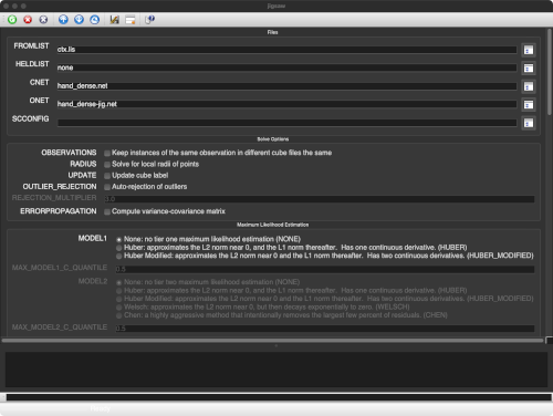
GUI Screenshot
jigsaw Linescan image example
Example GUI
The top of the GUI shows the parameters filled in for input cube list,
the input control network and the output control network. All other parameters
were left at their default values.
Input file defining the file names of the four cubes used in the control network.
The file names can include a path if needed. Each file name is on a separate line and
the last file name can have new line at the end, but it is not required.
Example 2
Run of jigsaw parameterized for Kaguya Terrain Camera (TC) images and a relative control network covering the Apollo 15 landing site.
Description
A relative network is a network that connects overlapping images with tie points but has no tie points connected to a ground source. Since there is no
connection to ground in the network, this bundle will only solve for camera specific parameters. The bundle could still solve for other parameters and be
correct relative to the camera position, but it would increase the complexity of the bundle. The proceeding two examples will include grounded networks,
so we will wait to increase the complexity of the bundle until ground points are included. Additionally, in this example we are evaluating the solution and
do not want to apply it to the images yet, therefore, update is set to ‘no’.
This relative bundle turns on and parameterizes the camera twist and camera acceleration solve parameters. Camera twist is a flag that allows the bundle to solve
for the camera's rotation around the bore sight axis and uses the same uncertainty estimation as the other two rotations. Setting the camera solve parameter to acceleration, however,
does require uncertainties to be set for the angles (deg), angular velocity (deg/s), and angular accelerations (deg/s**2). These values were set with increasing
constraint because of the increasing affect alterations of higher order parameters have on the bundle solution.
The ‘overexisting’ flag tells the bundle solution to approximate the camera rotation with a zero polynomial function added to the existing rotation data (adding the
polynomial over the existing data). Without the ‘overexisting’ flag, the bundle fits a polynomial to the existing rotations, throws out the existing data
points, and uses the polynomial to calculate the approximate ephemerides when needed.
This bundle also lowers the max iterations to 10 (from default 50). Lowering the max iterations does not affect the bundle solution. However, setting a lower
iteration limit can serve as a flag if you expect your network to bundle quickly. Finally, the sigma0 convergence criteria was not changed from its default
value, it was only explicitly stated in this call.
Run of jigsaw parameterized for Kaguya Terrain Camera (TC) images and an intermediate ground control network covering the Apollo 15 landing site.
Description
This example jigsaw bundle is run directly after adding ground control points to the previous relative network. With ground control points inserted into the
bundle solution, we will expand the bundle solve parameters to attempt solving for point radius values and the position of the spacecraft.
Ground points are weighted more heavily in the bundle than relative control points and adding parameters adds more complexity to the bundle solution. Therefore, it
is common to create and refine a network with only relative points and add ground point in after the relative network (and its bundle solution) is of sufficient quality.
The purpose of this bundle is to ensure the network bundle converges with the added ground points and solve parameters, before committing to updating the camera
pointing on the images, so update is set to 'no'.
In addition to the previous solve parameters, this bundle turns on the point radius and spacecraft position solve parameters. Applying the point radius solve
parameter requires the point_radius_sigma to be set. This value is a representation the uncertainty (in meters) of the cameras apriori pointing corresponding to the
correct elevation on the shape model; this value is not a hard constraint. Often this value can be set, and the appropriateness of the set value can be checked using
the 'POINTS DETAIL' section of the bundleout.txt file output by jigsaw. If more than half of the radius total corrections exceed the provided sigma, the uncertainty
may need to be increased.
Applying the space craft position solve parameter requires an uncertainty estimation through spacecraft_position_sigma (again this value is not a hard constraint).
The appropriateness of the provided sigma can be evaluated through the bundleout_images.csv X Correction, Y Correction, and Z Correction columns.
The 'overhermite' flag allows an estimation the spacecraft position like the 'overexisting' flag estimates the camera pointing, with a zero-polynomial added over
the existing data (for spacecraft position this is a cubic Hermite spline). These options require more memory but provide a solution more representative of small
variations in the original ephemeris data.
A shorten example of a typical bundleout.txt file produced by a jigsaw run with error propegation.
This file was trimmed to hold 10 images, 50 relative points, and all ground points
along with their associated detail sections. Bundleout files typically contain
all image and point from a network put through jigsaw.
Example 4
Run of jigsaw parameterized for Kaguya Terrain Camera (TC) images and a final ground control network covering Apollo 15 landing site.
Description
This last example is of a final jigsaw run of a grounded network. In this example all network adjustments are done, the bundle is converging, the resulting
residuals are acceptable, and therefore we are ready to update the camera pointing on the cubes. During the final run we turn on the error propagation flag, this
provides the variance-covariance matrix of the parameters, from which uncertainties can be computed. This is valuable if you plan to compute certainties for
your update cubes camera pointing (or any kernels resulting from these updated camera pointings).
If you want to double check the update was completed, see cathist or catlab (search for ‘Jigged’).
A shorten example of a typical bundleout.txt file produced by a jigsaw run with error propegation.
This file was trimmed to hold 10 images, 50 relative points, and all ground points
along with their associated detail sections. Bundleout files typically contain
all image and point from a network put through jigsaw.
Table summaries for the InstrumentPointing and InstrumentPosition tables extracted from
a jigsaw updated cube label. The InstrumentPointing table was updated due to the camera
updates solved for in the bundle (camsolve=accelerations). The InstrumentPosition table
was updated due to the spacecraft updates solved for in the bundle (spsolve=positions).